|
Weather Helm
by Lester Gilbert
On the pond, we know that the helm (the rudder angle we use)
of a sailing boat can be adjusted by either moving the sail plan forward to
reduce weather helm, or moving the sail plan back to increase weather helm. For
many years, I thought I understood weather helm, and I thought I understood why
most sailors want a little weather helm while sailing their boats. Let’s take a
quick run through this conventional wisdom on balance and weather helm.
To begin with, we imagine an ideally “balanced” boat is one
that sails her course “hands off” without any particular helm input, either
weather or lee. We have probably heard other sailors telling us that the rudder
is a device for creating drag, and that the boat makes her best speed if the
rudder remains neutral. If we sail competitively, we have also heard the advice
that a little weather helm is a good thing, however, because it allows the boat
to positively react to a change of wind direction, and so we need to put up with
this necessary evil in order to have a more responsive boat. Finally, we will
have carefully changed our mast rake (or moved the mast) as the wind built or
died during the day at an event in order to keep the boat “balanced,” probably
with only some small weather helm.
You might have guessed by now that I’m going to tell you this
is only a little bit right and all mostly wrong… Let’s see why.
Leeway
When beating against the wind, we know that the boat resists
the force of the wind, which is trying to push her sideways and off course.
Old-time sailors might talk about the “grip” of the boat in the water. What is
happening is that the boat, mainly the keel, pushes against the water and in
doing so makes leeway. The result of the push, or the leeway, is a lifting force
that keeps the boat more or less going where she is aimed. Not exactly where she
is aimed, of course, because the leeway is the difference between the boat’s
heading and her actual course. Generally the stronger the wind, the more the
leeway, which is really just another way of saying that more lifting force is
being generated by the boat to resist the stronger wind.
Leeway is like the angle of attack of a wing, and much as
with a wing, the leeway of a keel is what generates the lift needed by the boat.
Downwash from the keel
Now this is the science bit. Whenever a keel (or any other
device) generates lift, it also generates what is known as downwash, and
anything behind it, such as a rudder, experiences this downwash as a change in
the angle of the oncoming water. When the boat makes leeway, the keel is
generating lift, and there is downwash behind the keel. This is one of the
reasons it is not smart to sail close behind and to leeward of another boat.
Your rig will be in the downwash of the rig of the other boat and your keel will
be in the downwash of its keel.
Keel downwash in theory
Hoerner (1965) provides a theoretical formula for downwash
behind a wing, given the coefficient of lift being generated by the wing and the
wing’s aspect ratio, simplified and shown as Equation 1:

This classic result
can be derived from the “momentum theory of lift,” explained in
Momentum theory of lift.
A common choice when designing an appropriate fin for the
keel of a boat is to require the fin to provide a coefficient of lift of 0.3
when the boat is heeled at 30 degrees. In this case, Eq. 1 suggests the
resulting downwash behind a keel of aspect ratio 1 is approximately 5 degrees
(if the constant is 18.2). What is interesting about this formula is the simple
linear relationship between downwash and lift coefficient.
To connect the theory of Equation 1 with some of the
experimental data that we will look at shortly, it is useful to know the
connection between leeway and lift coefficient. A rough rule of thumb from basic
aerodynamics tells us that the lift coefficient, for small angles of attack
before stall, is approximately one-tenth the angle of attack. Airfoils develop
about 0.1 lift coefficient per degree of attack, counting from the angle of zero
lift. Using this rough estimate, if our keel has Cl = 0.3, say, then the boat is
probably sailing with around 3 degrees of leeway.
Flow around a hull
Marchaj has a picture of keel downwash in his book,
Aero-hydrodynamics, illustrated in
Figure 1.
The hull is heeled at around 30 degrees, as though it were beating on port, and
is making leeway against the flow of water.
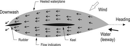
Figure 1.Underwater
view, looking “up,” of flow around a heeled hull with leeway
(based upon Photo 4.3 in Marchaj, 2000).
The flow indicators in Figure
1 are not as
clear as they could be, but we can see that the rudder is more or less in
alignment with the downwash at the stern of the hull. The rudder is not
“neutral” in this situation, and we can see that it is showing what we’d call
weather helm. If the rudder were “neutral,” it would not be aligned with the
local flow of water. Instead, the local water flow would be acting to generate
rudder lift so as to turn the hull into the wind, i.e., giving lee helm.
Figure 1
is our first suggestion that “neutral” helm is not the same as “no weather or
lee helm” and is not the same as “minimum drag.” On the contrary, if we set up
the boat to be “balanced” and have “neutral” helm, we have actually given it lee
helm, and we have not set it up with the lowest possible rudder drag.
Keuning experiments
Marchaj’s picture of keel downwash is pretty clear that when
we set “neutral” helm we actually give the boat lee helm, but we now need data
to calculate downwash. Keuning and collaborators tested a model with different
keels in a towing tank in 2006, looking at the downwash experienced by the
rudder when the model was towed with some leeway. It is worth looking at their
experiments in some detail. Figure
2
shows the profile outline of the model they used.
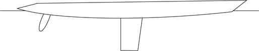
Figure2.
Hull model (based upon Keuning et al, 2006).
Figure
3
shows the three keels that were attached to the hull for the tests. Keel “A” is
the kind of high aspect ratio keel we might see on an International One Metre,
while keel “C” is the kind of low aspect ratio keel we might see on an
International A Class or a 36R.
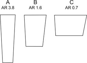
Figure
3.
Test keels and their geometric aspect ratio (based upon Keuning
et al, 2006).
While Keuning towed the model upright and at 15 degrees heel,
we’re going to look at the heeled data only. It turns out the upright data is
pretty similar. The key point here is that Keuning measured downwash by moving
the rudder until it gave zero lift, which is the point at which it gave minimum
drag. The angle of the rudder was therefore the angle of downwash as experienced
by the rudder. Figure
4
shows a graph of Keuning’s results, and there are a couple of points that are
worth making.
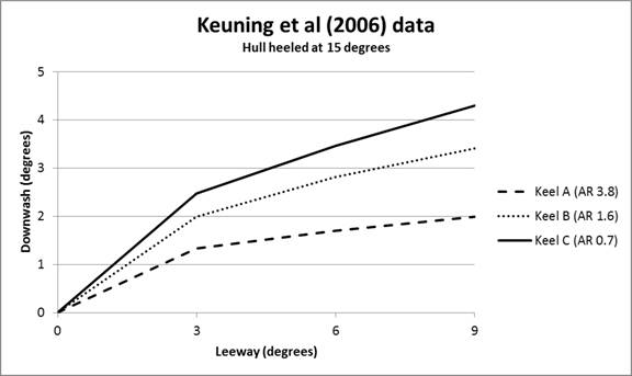
Figure
4.
Downwash experienced by the rudder for different keels at three
angles of leeway, hull heeled at 15 degrees (based upon Keuning
et al, 2006).
First, it is clear that high aspect ratio keels have less
downwash. Second, the amount of downwash increases with leeway. But the
relationship between leeway and downwash is a not a straight line; instead, they
are approximately exponential curves, and an exponent of 0.5 (a square root) is
a pretty good approximation.
The Keuning data suggests a quite simple formula
for the downwash experienced by the rudder in their experiment:

Equation 2 paints a rather different picture about the
relationship between downwash and lift. It suggests that, in practice, this
relationship is not the theoretical linear relationship of Equation 1 but is a
reducing exponential one, a square root.
The factor “1.34” in Equation 2 is merely an adjusting
constant that matches the experimental results from the leeway and keel aspect
ratios to the particular hull used, and we’ll improve this later on in the
article.
Implications of downwash for “balance”
If we are sailing a boat that looks anything like
Figure 2,
then we can read off some of these numbers. For example, an A Class might make
around 5 or 6 degrees of leeway in a blow, and with a keel aspect ratio (AR) not
too different from 0.7, the expected weather helm is around 3 to 3.5 degrees.
In this example, a perfectly “balanced” boat sails with
minimum drag at around 3 degrees of “weather helm.” That is usually considered
to be a lot of weather helm, and if I felt I had to push that amount of rudder
on the transmitter I’d be moving the rig forward very smartly! But wait! If you
give your boat neutral helm and set it up so that it sails “hands off,” you in
fact effectively give it lee helm (and you add drag) because the rudder is no
longer aligned with the perfectly normal downwash from the keel. If you move the
rig and position it to give your boat a little weather helm, just a touch like
everyone tells you to do of around 1 degree, nevertheless you have still
effectively given the boat lee helm and added drag.
Estimating “minimum drag” weather helm
The problem with our current radio control systems is that we
cannot know and cannot feel what the rudder “wants to do.” When sailing full
size, with a good breeze and good heel, you can feel the pressure on the tiller,
and it tells you where there is least pressure—i.e., least lift (which is when
there is least drag on the rudder)—and that is usually when it is some degrees
off neutral or centered.
[Ed. This is a vitally important point that can and should be
experienced in practice. Go and crew a full-size keel boat and helm it on the
beat, well-heeled in a good breeze. Heck, go and chat to keel boat owners and helms at your local sailing club.
This is your question: "On the beat, how far off the centre-line do you hold the
helm to keep the boat balanced when well heeled and making best VMG?"]
Our task now is to estimate the correct amount of helm to expect for our
radio-controlled model for minimum drag, and this is the same as estimating the
downwash in the vicinity of the rudder.
The first part of this task is to estimate a general value
for the amount of downwash the keel generates, and we can do that using leeway
and the keel aspect ratio in Eq. 2.
The next part of the task is to estimate how much of the keel
downwash is experienced by the rudder. Compare the relative distance between
rudder and keel shown in Figure 1,
and the relatively large separation between the rudder and the keel shown in
Figure 2.
In boats with the rudder closer to the keel we would expect the rudder to
experience higher downwash than otherwise. We’ll estimate the adjustment to the
downwash for rudder separation in a following section.
Then we may need to make an adjustment for any skeg in front
of the rudder. Modern radio-controlled boats have all-moving rudders, but older
boats and free sailing boats may have rudders hung at the end of a skeg.
Finally, we need some way of estimating leeway in order to
calculate expected weather helm. Leeway is very difficult to determine just by
looking at the boat sailing because common leeway angles for modern designs are
so small. For an IOM it might be 1.5 degrees in a moderate breeze. But in the
last section we’ll propose a solution based on heel, which is much easier to
see.
Rudder separation
Downwash is due to lift, and is the manifestation of the
circulation discussed in
Circulation theory of lift. The circulation around a keel generating lift is
considered to be centered on the keel quarter chord and has a given strength. As
we move away from the center of lift, although the circulation has a constant
strength, the actual downwash experienced naturally diminishes with increasing
distance.
If downwash of, say, 7 degrees is seen 1 m. away from the
keel, then we would expect to see downwash of 3.5 degrees 2 m. away, and so on.
In this case, we could say that the strength of the circulation was “7,” and a
rudder 0.5 m. away from the keel would experience 14 degrees downwash.
We can estimate the keel-to-rudder separation in the Keuning
experiment as follows. Figure 2 shows Keuning’s “keel 1” fitted, and Keuning
tells us this keel has a mean chord of 0.23 m. Some measuring with a ruler tells
us that the center of lift of the rudder is thus approximately 1.09 m. away from
the center of lift of the keel.
Keel downwash using Keuning data
Equation 2 estimates downwash for a rudder 1.09 m. away from
the keel. We can adjust the formula so that it gives a “standard” downwash for a
rudder at a “standard” separation of 1 m. Then, knowing the actual separation
for a particular boat, we can estimate the actual downwash by dividing by the
actual separation. This gives us the formula we will now use to estimate weather
helm for a variety of classes as Equation 3:

Skeg
The effect of the skeg needs some careful analysis, and what
follows is a simple start, which is undoubtedly not completely accurate.
First we note that a skeg is used by free-sailing boats to
improve directional stability.
Also, the effect of the skeg is to reduce (dampen) the
effectiveness of the rudder. For example, an all-moving (no skeg) rudder angle
of 3 degrees has very roughly the same effect as a skeg-mounted rudder angle of
6 degrees if the skeg has the same chord as the rudder.
For our purposes here (estimating the minimum drag rudder
angle, which is aligned with the downwash experienced by the rudder) to a first
approximation, we can ignore any skeg.
Classes
We consider four different classes and their typical aspect
ratios and rudder separations, as shown in Table
1.
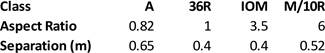
Table
1.
Aspect ratio and rudder separation parameters for different
classes.
Estimating leeway
To use Eq. 3 we need to know rudder separation, keel aspect
ratio, and leeway. The first two are straightforward to measure, are strongly
associated with a particular class of boat, and are shown in
Table 1.
The tricky part in using Eq. 3 is estimating the leeway a boat might make.
About the only easily observed visual indicator we have about
a boat sailing, and about the lift being generated by its keel, is the amount of
heel it shows. In general terms, the stronger the wind the greater the heel, and
the stronger the wind the more lift needed from the fin and hence the more the
leeway. So leeway and heel angle are closely connected. The problem we have is
that if one boat has a wider beam than another it will show less heel; if one
boat has a smaller fin that another, it will show more leeway; and so on for
draft, ballast, and a number of other factors that get in the way of any simple
relationship between leeway and heel. Our solution is to use a fudge factor.
In general, boats within most classes are broadly similar
with regard to displacement, beam, and so on. What most distinguishes one class
from another is the class rule restriction on draft, and where draft is
restricted, boats will likely have lower aspect ratio, less efficient fins. And
we know that less efficient fins need more leeway to generate the lift their
boats need. Another way of saying this is that less efficient keels make more
leeway, all other things being equal. So the fudge factor is to decrease
estimated leeway in proportion to increasing AR for a given angle of heel. We’ll
use the square root of the AR as our decrementing factor.
Modest angles of heel (up to, say, 30 degrees) are a function
of the sail force, as is the required lift coefficient to resist it. Another way
of saying this is that the lift coefficient, the angle of leeway, and the heel
angle, are in linear proportion.
To give a starting point, we’ll say (pretty arbitrarily!)
that a boat with keel AR = 1.0 gives 5 degrees of downwash when heeled at 30
degrees. (We mentioned this as a ball-park figure earlier, given by Eq. 1, where
we considered that the keel was giving a lift coefficient of 0.3.) We’ll scale
this by the square root of the AR of the class we are interested in, and then
use Eq. 3 to estimate weather helm. The result is
Figure 5.
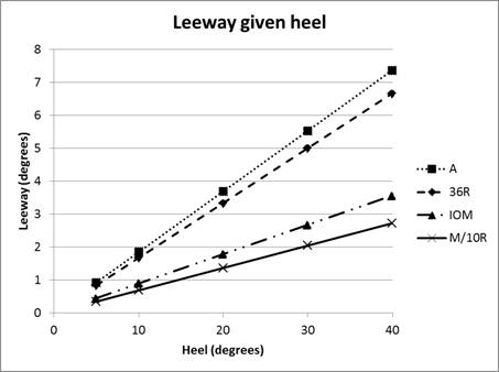
Figure
5.
Estimating leeway from heel for four different classes.
Estimating weather helm
Using heel angle as a proxy for leeway, and using our “square
root of AR” as a fudge factor to convert heel angle to an estimate of leeway for
different classes as shown in Figure
5,
Figure 6
uses Eq. 3 to give us the estimated weather helm we are seeking.
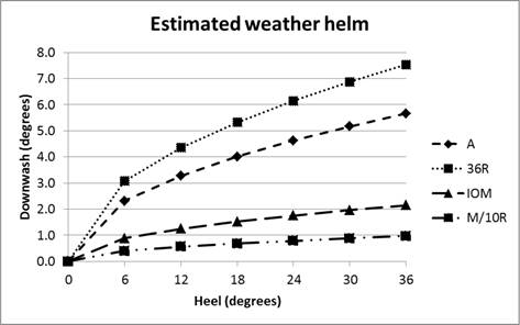
Figure
6.
Estimated “minimum drag” weather helm (downwash) depending upon
heel for four different classes.
We can useFigure 6
to estimate the kind of weather helm we should deliberately set when adjusting
our mast position for a given wind. For example, suppose we are sailing an IOM
and go for a test sail. Imagine we find we are heeling at 18 or 20 degrees. From
the graph, we can see that we should adjust mast rake (rig position) to give us
around 1.5 degrees weather helm at the transmitter. More dramatically, suppose
we are sailing an A Class and find she heels at 30 degrees—so we would set the
rig to give 5 degrees weather helm at the transmitter. Of course, to do any of
this scientifically, we will first have calibrated our transmitter so we know
many clicks on the trim button correlate to one (or 5) degrees of rudder
movement.
Conclusions
Naturally, you may be rather sceptical by this point. Five
degrees of weather helm gives minimum rudder drag? Seriously?
The first conclusion
is, well, yes, seriously: there is downwash off your keel that affects your
rudder, and setting “neutral” helm in fact sets lee helm. That’s pretty clear.
But 5 degrees? Ah, OK, well, the
second conclusion is that you’ll
have to make up your own fudge factor to suit your boat and your preferred
sailing style. You will have noticed that not even the experts can agree on the
exact relationship between leeway and downwash at the rudder. Some think it a
linear relationship; others think it an exponential. Have fun with that!
And what about the business of adjusting mast rake as the
wind builds or dies, because we find our boat sails with increasing weather helm
in the first instance or, worse, gains lee helm in the second? Well, this
analysis suggests that you may need to adjust mast rake, but not for the reasons
you thought, and not by the amount you’ve done previously. So our
third and final conclusion is that
the purpose of adjusting rake is to actually dial in a particular amount of
weather helm needed by the boat and our sailing style according to the
conditions. In many situations, it might mean leaving the mast where it is,
because increasing weather helm with increasing wind is what the boat requires
and does not need to be dialed out. What is therefore needed is a much more
skilled, anticipatory, and sensitive thumb on the rudder stick. But I guess you
knew that already!
References
A. Marchaj (2000). Aero-hydrodynamics. Adlard Coles.
S.F. Hoerner (1965). Fluid Dynamic Drag, Author.
J. A. Keuning, M. Katgert, and K. J. Vermeulen (2006). Keel—Rudder
Interaction on a Sailing Yacht. In 19th International HISWA Symposium on Yacht
Design and Yacht Construction, Amsterdam. Downloaded from (www.hiswasymposium.com/assets/files/pdf/2006/Keuning@hiswasymposium-2006.pdf)
Acknowedgements
Graham Bantock gave valuable comments on an earlier draft.
The errors are all mine.
|
.htm_cmp_lghome010_bnr.gif)