|
SAILSetc have prepared a special Italiko for me. I asked if a couple of
things could be provided, and they came up with all the ideas and
implementation. Here are some details.
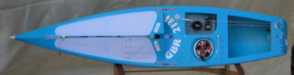 An
overhead view shows that she has a strong resemblance to an Ikon -- not too
surprising given that she is indeed an Ikon with a "strip" removed
along the centre plane. The servo tray is now located on one side, and the
radio pot on the other. You can have the radio pot recessed under a deck
patch if you really want this, but I've opted to have the screw-top lid to the
pot accessible directly. Much better if there is any chance you'll need to
get to the Rx to change frequency, or to get to the battery for a longer
event. It now makes it a much more realistic option to run with a small,
light, low capacity Rx battery pack. Such a pack can be replaced every
fourth race, say, and allows you to put the 100 gm you've saved into corrector
weight right on the bottom of the hull where it will do most good. An
overhead view shows that she has a strong resemblance to an Ikon -- not too
surprising given that she is indeed an Ikon with a "strip" removed
along the centre plane. The servo tray is now located on one side, and the
radio pot on the other. You can have the radio pot recessed under a deck
patch if you really want this, but I've opted to have the screw-top lid to the
pot accessible directly. Much better if there is any chance you'll need to
get to the Rx to change frequency, or to get to the battery for a longer
event. It now makes it a much more realistic option to run with a small,
light, low capacity Rx battery pack. Such a pack can be replaced every
fourth race, say, and allows you to put the 100 gm you've saved into corrector
weight right on the bottom of the hull where it will do most good.
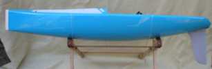 A
side view shows the shape of the rocker. If you are a designer, this'll
tell you more than it tells me right now, but I see quite a long entry, quite a
shallow entry angle, with maximum rocker aft of mid-hull. Like the current
crop of the SAILSetc designs, she has a peaked foredeck, giving a powerful, high
mast ram, and high mast partners which clamp the mast as a cantilever and
thereby increase its effective stiffness four-fold. Really. A
side view shows the shape of the rocker. If you are a designer, this'll
tell you more than it tells me right now, but I see quite a long entry, quite a
shallow entry angle, with maximum rocker aft of mid-hull. Like the current
crop of the SAILSetc designs, she has a peaked foredeck, giving a powerful, high
mast ram, and high mast partners which clamp the mast as a cantilever and
thereby increase its effective stiffness four-fold. Really.
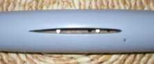 In
order to get the position and inclination of the bulb millimetre-perfect, a pair
of small M2 machine screws are tapped into the base of the bulb's slot.
Screw 'em in, or screw 'em out, to raise and lower the bulb nose or tail.
Very effective. In
order to get the position and inclination of the bulb millimetre-perfect, a pair
of small M2 machine screws are tapped into the base of the bulb's slot.
Screw 'em in, or screw 'em out, to raise and lower the bulb nose or tail.
Very effective.
Update: Did I say the machine screws in the bulb slot were
good? I now tune my bulb cant for every event, easily and quickly, by
dialling in exactly the amount of nose-up I want with a quarter- or half-turn of
a screw. Very slick.
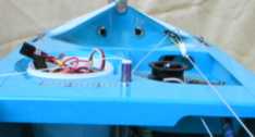 This
is a view looking forward. In the distance are two switches set into the
bulkhead, under the foredeck flange, one for On/Off, and one to program the RMG
winch 'cos my radio system is "intelligent". Also under the
flange is a turning block for the sheeting line to the mainsail. In the
foreground is the main sheet post, which I have as low as possible, rather than
higher up, tucked under the boom. The current arrangement has the post
adjustable as a friction fit, and works very well if it tucks under the boom,
but otherwise the post needs to be screwed in place if it is to take the
sheeting loads associated with "vang sheeting". Then, if you do
screw it in place, you need to have greased it well beforehand, and to
periodically remove it from the hull, otherwise it seizes in place, particularly
if you sail in salt water. You'll also note that the lip to the servo tray
has been cut back a little to allow the sheeting line to run from the winch to
the rear thru-deck fitting. This cut-back is needed if you are running a
step-down or snail drum, and not if you run a "normal" single or
double drum. This
is a view looking forward. In the distance are two switches set into the
bulkhead, under the foredeck flange, one for On/Off, and one to program the RMG
winch 'cos my radio system is "intelligent". Also under the
flange is a turning block for the sheeting line to the mainsail. In the
foreground is the main sheet post, which I have as low as possible, rather than
higher up, tucked under the boom. The current arrangement has the post
adjustable as a friction fit, and works very well if it tucks under the boom,
but otherwise the post needs to be screwed in place if it is to take the
sheeting loads associated with "vang sheeting". Then, if you do
screw it in place, you need to have greased it well beforehand, and to
periodically remove it from the hull, otherwise it seizes in place, particularly
if you sail in salt water. You'll also note that the lip to the servo tray
has been cut back a little to allow the sheeting line to run from the winch to
the rear thru-deck fitting. This cut-back is needed if you are running a
step-down or snail drum, and not if you run a "normal" single or
double drum.
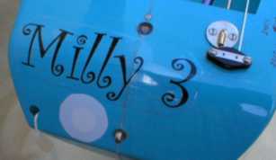 A
close view of the transom shows a number of features. On the right is the
thru-deck fitting that takes the line from the winch and feeds it to a turning
block. This block is a "Hales" with measurably lower friction
than, erm, some others I'm not going to mention. In the centre of the aft
deck is the new rudder post upper bearing, secured by a screw. The round
white patch on the transom covers an access hole for the tiller arm, making it
very much easier to remove the rudder than before. And yes, she's called
"Milly 3" in honour of my main supporter and long-time, ah, sponsor. A
close view of the transom shows a number of features. On the right is the
thru-deck fitting that takes the line from the winch and feeds it to a turning
block. This block is a "Hales" with measurably lower friction
than, erm, some others I'm not going to mention. In the centre of the aft
deck is the new rudder post upper bearing, secured by a screw. The round
white patch on the transom covers an access hole for the tiller arm, making it
very much easier to remove the rudder than before. And yes, she's called
"Milly 3" in honour of my main supporter and long-time, ah, sponsor.
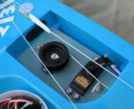 A
close-up of the servo tray shows that the winch and rudder servo are mounted on
a simple tray, that is screwed down in the opening. I've put a simple
hooked piece of 3 mm aluminium rod next to the rudder servo to guide the
sheeting line away from the rudder horn as it approaches the winch. This
is needed 'cos the RMG step-down drum has a counter-clockwise spiral, and feeds
on the right. A clockwise spiral would feed on the left, and the line
wouldn't have to be kept away from the rudder horn in this case. A
close-up of the servo tray shows that the winch and rudder servo are mounted on
a simple tray, that is screwed down in the opening. I've put a simple
hooked piece of 3 mm aluminium rod next to the rudder servo to guide the
sheeting line away from the rudder horn as it approaches the winch. This
is needed 'cos the RMG step-down drum has a counter-clockwise spiral, and feeds
on the right. A clockwise spiral would feed on the left, and the line
wouldn't have to be kept away from the rudder horn in this case.
The pot holding the Rx and battery is specially shaped. A lower segment
has been cut off it (not visible in the photos) and a flat plate fitted instead
so it can recess in the hull without fouling the side of the boat.
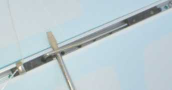
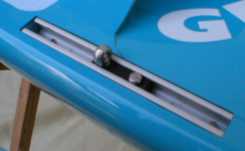 Here
is the first "special" feature -- a length of deck track that has been
recessed for the shroud attachment to the gunwale. The idea is that it
allows a far wider range of shroud attachment points than normal. The
track is in fact pierced with holes at regular intervals, and the set-screw on
the slide is longer than normal, so it sets into a hole. Here
is the first "special" feature -- a length of deck track that has been
recessed for the shroud attachment to the gunwale. The idea is that it
allows a far wider range of shroud attachment points than normal. The
track is in fact pierced with holes at regular intervals, and the set-screw on
the slide is longer than normal, so it sets into a hole.
Update: I've now had a chance to see how this works, and it
works well. One change I have had to make, however, is to space the holes
more closely together. It turns out that the mast bend is very
sensitive to shroud attachment position on the hull. Just a small shift in
shroud position can bring a bunch of wrinkles into the mainsail luff.
Internally, the hull has been particularly strengthened at the chain-plate
area to take higher than "normal" shroud tensions, and shroud tensions
which act further aft than "normal" as well.
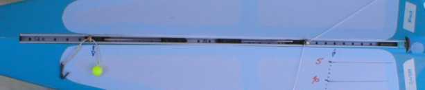
A similar idea has been applied at the foredeck, where a long length of deck
track has been recessed to provide both pivot points, and sheet reeving
points. The regular holes in the track are clearly visible, and they allow
complete freedom to choose the pivot point and the sheeting radius in any
rig. The mast ram is set into the end of the track.
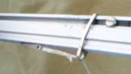
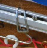
 The
track slides are set in position using a spring-loaded "pin" instead
of set screws, as illustrated. The "spring" and "pin"
are simply a length of stainless steel wire in an "L" shape, with the
long end of the spring set into a second track slide, seen on the right of the
picture. The pin end secures the eyebolt slide, on the left of the
picture, by passing through the hole that normally takes the set-screw, and
locating in one of the track holes below. Very effective, quick and easy
to change and adjust. The
track slides are set in position using a spring-loaded "pin" instead
of set screws, as illustrated. The "spring" and "pin"
are simply a length of stainless steel wire in an "L" shape, with the
long end of the spring set into a second track slide, seen on the right of the
picture. The pin end secures the eyebolt slide, on the left of the
picture, by passing through the hole that normally takes the set-screw, and
locating in one of the track holes below. Very effective, quick and easy
to change and adjust.
The whole point of these recessed tracks, of course, is to be able to vary
jibstay and topping lift tension by varying pivot offset and shroud offset, as
per the pages on rig tensions, and as
permitted by the special rigging fittings, below.
Update: The adjustable pivot point and sheeting point are
excellent. Almost too good in a way, because I've got myself into a muddle
more than once by making too many changes and losing what little tune I
had. You do need a clear head as you shift the pivot and sheet reeving
points to be sure you are doing the right thing. Leave 'em alone if you're
just messing about!
 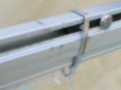  The
second "special" feature is the use of prototype SAILSetc boom
fittings. The special fitting is a laser-cut stainless steel item that
effectively provides an eye for the boom, much like a boom band for an arrow
shaft boom. They slide up and down and can be locked in any
position. The fitting has a very small peg that locates in the hole found
in the standard boom slide. The fitting replaces the little shackle that
some skippers use at the aft end of the boom for the sheet attachment, and
provides the pivot arrangement at the forward end. These two pictures show
the fitting being used to locate the pivot on my No.1 rig, which is a length of
line that hooks into one of a row of holes under the boom. The length of
line, the hook, and its attachment to the deck are shown in the earlier picture
of the foredeck and the deck track. The
second "special" feature is the use of prototype SAILSetc boom
fittings. The special fitting is a laser-cut stainless steel item that
effectively provides an eye for the boom, much like a boom band for an arrow
shaft boom. They slide up and down and can be locked in any
position. The fitting has a very small peg that locates in the hole found
in the standard boom slide. The fitting replaces the little shackle that
some skippers use at the aft end of the boom for the sheet attachment, and
provides the pivot arrangement at the forward end. These two pictures show
the fitting being used to locate the pivot on my No.1 rig, which is a length of
line that hooks into one of a row of holes under the boom. The length of
line, the hook, and its attachment to the deck are shown in the earlier picture
of the foredeck and the deck track.
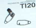
 The
idea is extended to provide for a ball-raced pivot fitting. Two of the
stainless steel fittings are joined together around a ball race. A wire
hook locates in the ball race and attaches to deck, and the whole assembly can
then slide along the boom. In fact a couple of prototypes were needed to
get this just right, since the fitting is not symmetrical -- the aft side of the
housing needs to be longer than the forward side, so the ball race is held at
the correct angle to the boom. This fitting is shown on my No.2 rig, where
there is less of a need to adjust the length of the pivot. The
idea is extended to provide for a ball-raced pivot fitting. Two of the
stainless steel fittings are joined together around a ball race. A wire
hook locates in the ball race and attaches to deck, and the whole assembly can
then slide along the boom. In fact a couple of prototypes were needed to
get this just right, since the fitting is not symmetrical -- the aft side of the
housing needs to be longer than the forward side, so the ball race is held at
the correct angle to the boom. This fitting is shown on my No.2 rig, where
there is less of a need to adjust the length of the pivot.
If any of these new fittings interest you, please contact SAILSetc
for details on availability and pricing. Tell 'em Lester sent you...
Update: I've had a chance to sail the Italiko in a number of
events, and I can report excellent news. I find her just as fast as the
Ikon in all points of sailing, and almost certainly faster on the run. She
changes her balance (helm) much less violently than the Ikon, and I've not yet
experienced "snap" weather helm. She'll still develop lee helm
in the lulls and weather helm in the puffs, but it is all much more
controllable. So when the breeze is at the top of "A" rig, I
find I can keep up with other Ikons just because she is easier to sail, and the
slightly narrower beam (and hence slightly lower stability) doesn't really seem
to matter that much. Now if only I can learn to race better...
2005-12-18 |