|
3D Printed Sail Box Fittings
by Lester Gilbert
A new sail box for the 2018 10R World Championships in
Germany seemed a good simple starter project for my new-to-me 3D printer.
I’d kept my 10R rigs in individual plastic sail bags previously, which
did not make for quick rig changes if needed.
3D printing
To test the home 3D printing waters I had purchased a
second-hand Lulzbot ‘Mini’ using 2.85 mm filament.
The Mini has a modest build volume of around 6” x 6” x 6”, fine for the
small things I wanted to make, and some useful features which I have come to
greatly appreciate – automatic bed levelling;
automatic nozzle cleaning; a
heated bed with a PEI coating; an
all-metal hotend; interchangeable tool
heads; highly configurable driver and
slicer software (Lulzbot ‘Cura’) pre-loaded with printing profiles for a range
of filaments; an open architecture;
and readily available manuals, guides,
help, and parts from the Lulzbot Web site.
I had previously worked with a Flashforge Dreamer at the University of
Southampton with rather mixed results, and was initially nervous of any
substantial investment.
[Ed. Lulzbot ceased trading for a while, but on their return they targeted
the commercial, rather than the consumer, market, with prices to match.
When I was ready to move to a larger build table I invested in a Prusa Mk3
instead, it has been quite excellent.]
My continued association with the University as an ‘Emeritus
Fellow’ allowed me to use its licence for an industrial strength 3D CAD
application, Dassault ‘Solidworks’.
The learning curve for any 3D CAD is quite steep, and I found it more or less
vertical for this software which is otherwise used to design jet aircraft.
Fortunately, I could access some good tutorial and training materials to
help me along. For anyone new to 3D
printing, securing good consumer-grade (rather than DIY hobbyist) hardware is
reasonably straightforward, but finding and learning 3D CAD design software is
likely to be somewhat more challenging.
Designs
My previous sail boxes used clips to hold the masts, and I
found that, over time, they marked the soft aluminium or scratched the carbon
fibre. I then tried plastic-coated
clips, but found they were not suited for outdoor use, the plastic degraded and
then disintegrated and the clips rusted.
For this sail box, I went with a cup to hold the mast head and backstay
crane, and a loop and step to hold the mast heel, as illustrated in
Figure 1
and Figure 2.
There were two design details of significance.
One was to match the depth of the cup to the drop between the loop and
the step of the heel fitting, so that there was enough room to place the rig in
the cup before dropping the heel through the loop onto the step.
Yup, there went a couple of early prototype prints into the bin before I
fully understood that inter-relationship.
Two was to make the cup a little wider than simply the diameter of the
mast plus a little allowance. This
was because the mast is inserted at an angle, and some distance, into the cup
before it can be positioned above and dropped into the retaining loop at the
heel. Yup, there went another
prototype print.
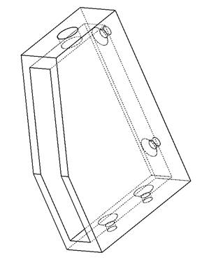
Figure
1.
Masthead cup fitting in initial wireframe display.
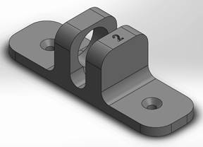
Figure
2.
Mast heel fitting in final isometric surface rendering.
For a little bling, I decided to decorate the box with corner
scuff plates and to provide some reinforcement, one such plate illustrated in
Figure 3.
Using 3D CAD and 3D printing meant I could easily fabricate a corner
plate that was, for example, 104 degrees to suit the angle of the box’s leech
run, or 85 degrees to suit the box’s angled base for upright stability when
opened.
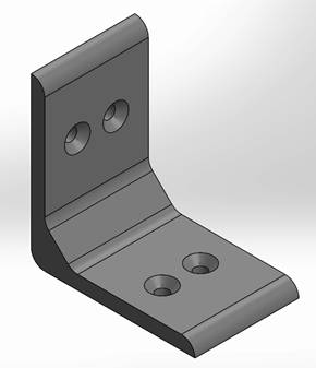
Figure 3.
Corner reinforcement.
I sketched out the sail box in Corel Draw, a 2D vector
drawing application. The layout of
the box panels is illustrated in Figure
4.
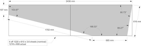
Figure
4.
Box panels laid out in Corel Draw.
The box build didn’t go well.
I cut out the 3.2 mm plywood panels separately and then found slight
dimensional differences between the left hand and right hand panels (should have
cut the left and right panels as one).
I cut the left and right panels using the pattern on the same hand and
found that, when mirrored, they then sagged in the same direction, with the left
panel sagging convex and the right panel sagging concave (should have mirrored
the wood before cutting). I decided
to go for a ‘neat’ build, rebating and mitering the lid battens.
Now while the plan might have called for a 52 degree mitre to give the
104 degree angle between two battens, for example, I simply didn’t have the
woodworking skills (or the sufficiently accurate fence) to cut a 52 degree mitre.
I think it turned out to be around 55
degrees and not square to the batten which was enough to make the join a little
wobbly rather than firm. I failed
to learn from my mistake with the panels, and again cut the rebates using the
template on the same hand. When
mirrored to give me left and right, well, all the rebates on one half were on
the wrong side. I decided the sail
box needed to tip forward by 10 degrees to have upright stability when opened,
so I angled the base of each lid by 10 degrees.
Wrong, the total tip needed to be divided between the lids, and each base
should have been angled by something like 5 degrees (well, 7 degrees, being 10*cos(45),
if the lids were to be opened to 90 degrees).
But I now know how to make wizard sail boxes.
Prints
None of the printed fittings were intended for longevity,
instead being vehicles for learning my way around the Lulzbot Mini printer, the
Cura driver and slicing software, and the Solidworks 3D CAD application.
I decided to print using PLA filament, which has the two advantages of
being an easily printed material, and of being biodegradable following the
inevitable errors and breakages.
The results are illustrated in place in the following photos.
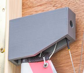
Figure
5.
Masthead cup fitted in the box.
The cup took a few prototype prints before I was satisfied.
The nature of 3D filament printing is that material overhang
(ie material which is unsupported during
printing) should be avoided, meaning the cup could not be printed on its side or
end but only with its opening uppermost.
This meant that the interior of the cup cooled rather more quickly than
the cup walls, such that the base lifted away from the print plate at the
corners. The first few prints were
abandoned as the cup slowly turned into a hollow squared-off banana.
Interestingly, the fix was to increase tool head cooling to the model to
reduce the subsequent temperature differential between wall and base.
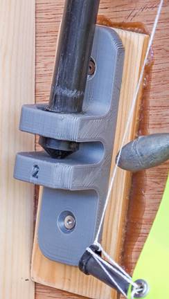
Figure
6.
Mast heel fitted in the box.
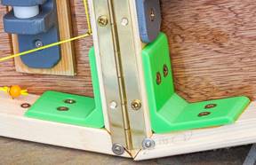
Figure
7.
Corner reinforcements in the box.
If I were to revisit the project, while I might prototype in
PLA again, I would make final prints in a less brittle material, perhaps
co-polyester (nGen, nVent), nylon, bridge nylon, ABS, ASA, or similar.
When screwing a fitting to the box, I found that there was a *very*
narrow range of torque between fixed to the wood but wiggle-able, so not quite
fixed enough, and fixed to the wood but now cracked along one of the filament
layers (yup, it was ‘fixed’, there went some more prints into the bin).
That range would have been a little wider with one of the alternative
filament materials mentioned. I
knew already that you couldn’t screw any of these thermoplastics tightly (as in
using a wood screw through an unreinforced hole), but hadn’t appreciated just
how brittle they were. They were
more than adequately strong, but rather prone to local compression failure.
|
.htm_cmp_lghome010_bnr.gif)