![]()
![]()
![]()
![]()
![]()
![]()
|
|
|
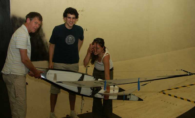
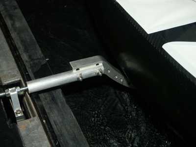
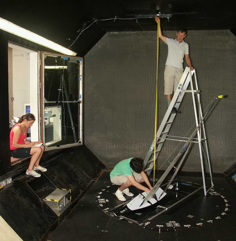
Mike, Gonzalo, and Jessica adjust the heeling attachment The apparatus was a development from the IOM heeling cradle tested in previous years. This comprised a semicircular section of thick-walled aluminium (a short length of 250 mm diameter pipe, cut in half) with arms running forward and supports on either side to the three dynamometer mounting points. Attached to the semicircular plate is a flange or tongue which engaged the fin box; the tongue can be moved around the plate to angle the hull.
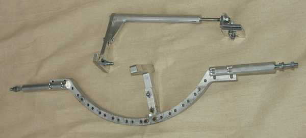
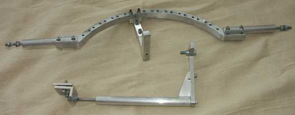
First design for heeling apparatus The design was effective, but had two drawbacks. One was the difficulty of returning to an exact heel setting, since there was no indexing of the tongue position. Two was the twist on the fin box since the bows were not attached anywhere. An improved design for the "A" provided mounting holes spaced at intervals which would provide repeatable heeling angles of exactly 0, 10, 20, 30, etc degrees.
Indexed heeling positions design
As constructed
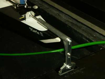
In position The bows were attached separately.
Bows attachment design
As constructed
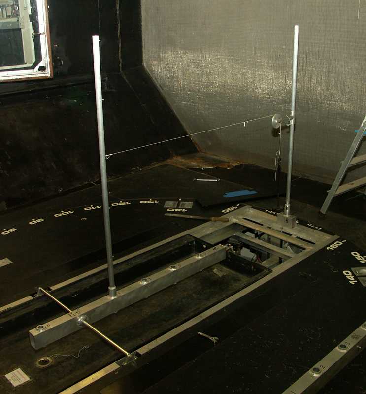
In position The resulting apparatus was constructed in the University's engineering support workshop.
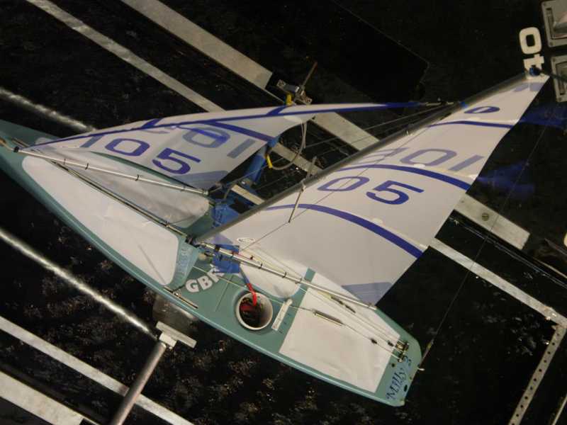
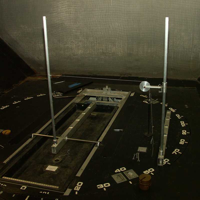
Set up on the turntable
Measuring camera to boat distances At the start of the experimental sessions, the dynamometer is calibrated in the drive axis and the heel axis by hanging weights and checking the computer readout.
Drive axis calibration
Heel axis calibration We await with interest the results of Jessica's upwind tests and Gonzalo's downwind tests. 2008-09-26 |
|
©2025 Lester Gilbert |