![]()
![]()
![]()
![]()
![]()
![]()
|
|
|
Stiffness
by Lester Gilbert and Graham Bantock
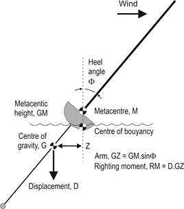
Figure 1
Geometry of a heeling yacht Balance
Consider a heeled boat in
balance or equilibrium, the force of the wind on the sails being balanced by the
lump of lead at the end of the fin, as illustrated in Figure 1.
The righting moment produced by the weight of the boat depends upon the
amount to which the boat’s transverse centre of buoyancy moves to leeward as the
boat heels. The point on the boat’s centreline directly above the transverse
centre of buoyancy is known as the Metacentre, M for short. The Metacentric
Height, GM, is the distance of this point above the centre of gravity, G. For
normal IOM hull shapes and normal heel angles the metacentric height varies very
little and it is reasonable to consider M as a fixed point.
The righting moment, then, is
the product of the boat’s displacement and the distance GZ, the righting “arm”,
which depends upon the sine of the heel angle.
It is obvious that the righting moment increases as the heel angle
increases.
Generally speaking, the relationship between wind speed and height above the water surface is logarithmic. (See the “wind gradient” topic at http://www.onemetre.net/Design/Gradient/Gradient.htm.) At zero height above the water, then, wind speed will also be zero. This is simply another example of the boundary layer effect that allows dust to remain on your car even though you have driven it fast. Two is that the sail area projected to the wind becomes vanishingly small as the boat is blown over, proportional to the cosine of the heel angle.
Arm
The ability of the boat to
resist heeling depends on the depth of the vertical centre of gravity (VCG,
highly dependent on the length of fin), and also upon the metacentric height
(which depends on the beam of the boat).
In the IOM class, since almost all boats have a draught of 420 mm, almost
all bulbs are around 2.35-2.4 kg in weight, and almost all boat and rig
construction weights are the same, the VCG is virtually fixed, and is
approximately 90 mm (No 1 rig) or 225 mm (No 2 rig) below the waterline.
It is therefore the variation of the metacentric height that provides the
differences in the righting moments of boats and this depends upon the
differences in their beams. As a
thought experiment, we can imagine an IOM hull that is a simple cylinder.
Such a hull would have a metacentric height of 0, since its metacentre
would coincide with its centre of buoyancy, but it would have a righting arm,
approximately 56 mm.
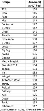
Table 1
IOM design arm
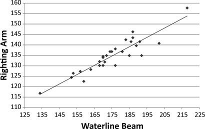
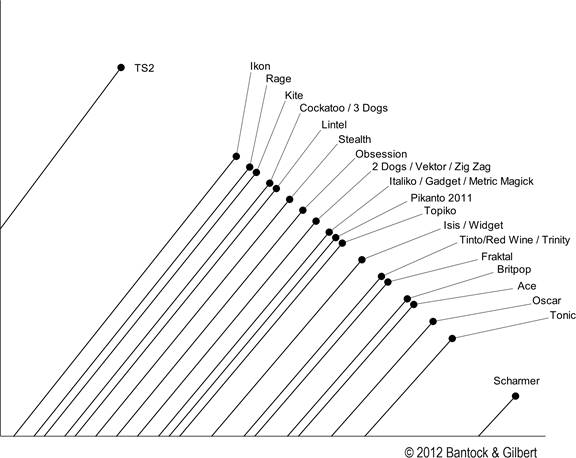
Figure 2
Righting arm versus waterline beam for a variety of IOM
designs Data
courtesy of ©2012 Graham Bantock Heel
My question at this point is,
“So what?” What practical
difference is there between the 158 mm arm of a TS2 and the 134 mm arm of my
Pikanto, or the 117 mm arm of the Scharmer?
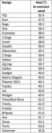
One way to look at this is to ask how much these different designs would
heel at a given wind strength. The
“average” design here is the Pikanto, and I calculated the notional wind
strength that would cause a Pikanto to heel at approximately 40 degrees.
I then calculated how much the other designs would heel in this notional
wind. In order to do this, I
estimated the centre of effort of the sail plan as approximately 740 mm above
the waterplane.
Table 2 IOM
design heel
Figure 3
Heel angles visualised at constant wind Effective and equivalent bulb weights
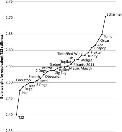
A second, and perhaps more
impactful way to look at this is to ask how much a lower arm and a higher heel
angle means the boat has a lower effective bulb weight.
That is, if we imagine a TS2 with a nominal 2.4 kg bulb that heels at
35.4° in a given wind, what is the “equivalent”, lighter, bulb that would see it
heel at 43.8° like the Scharmer design?
It turns out that this would be a 2.17 kg bulb.
Another way of saying this is that a TS2 would heel at 43.8° in the same
given wind if it had a 2.17 kg bulb.
My Pikanto, an “average” design, heels at 40.1° in this wind.
It has an “equivalent” bulb of 2.27 kg by comparison with a TS2 – that
is, a TS2 would heel at the same 40.1° in the same wind if it carried a 2.27 kg
bulb. Ah!
The results for other designs are shown in Table 3.
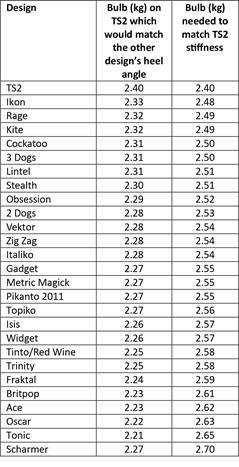
Table 3
IOM designs’ “equivalent” bulb weights
Figure 4
Required bulb weight to
match TS2 stiffness |
|
©2025 Lester Gilbert |