![]()
![]()
![]()
![]()
![]()
![]()
|
|
|
Fin forceThe first thing to understand is that the fin, acting under the water, is balancing the sail forces developed in the air. As the wind comes up and the sails develop more drive, the fin has to develop "opposite" lift in order to keep the boat more or less on course. In order to develop lift to oppose and thus balance the sail forces, the boat must sail at an angle in the water, an angle we otherwise know as leeway. Typically, an IOM might sail at a leeway angle of about 3 degrees in No.1 rig over much of the wind range. (Leeway develops for boats with "simple" symmetrical fins. If the fin has an effective trim tab, or has articulated multi-elements, it can develop lift at zero leeway.) The amount of lift developed by a foil is given by the formula
D is the density of the fluid. In air, D is about 1.2 if area is measured in square metres and speed is measured in metres per second. For fresh water, D is 1000. Let's imagine our IOM is sailing in a 4 m/sec breeze, and the boat is moving along at, say, 1.1 m/sec. We are in No.1 rig, with a sail area of about 0.6 sq.m, and if the sails are developing a coefficient of lift CL of around 1.0, total sail lift (in Newtons; around 9.8 Newtons to a force of one kilogram) is about
The two values match reasonably... Of course, I've chosen representative, but realistic, values to obtain this balance. There are three parameters which affect the amount of lift force the fin develops, as shown by the formula: fin area, lift coefficient, and boat speed. The boat speed is (more or less) given, so you are left to trade off the lift coefficient against fin area. More area, more lift, lower coefficient of lift needed, and so less leeway. The picture is trying to illustrate that the fin force comes from the fin "flying" through the water at an angle of attack equal to its leeway. Off the wind, the fin is a drag appendage, and on the run more fin area is bad because of wetted area drag. While beating, fin drag comes from two sources: wetted area, and induced drag. Induced drag depends on the square of the fin lift coefficient, and more area gives lower loading and lower induced drag for a given amount of lift. On the wind, more fin area is generally good. (But see "Update 2 (b)", below, for Graham Bantock's comments.) So the actual fin area you use is a compromise between the performance you want on the wind, and off the wind. Aspect ratio
where "AR" is the aspect ratio of the fin. High aspect ratio fins give less induced drag. If our AR = 4 fin is developing CL = 0.2, then we can estimate CDi is about 0.003. The aspect ratio also affects how well a given aerofoil section performs in "real life". A higher aspect ratio means the section lift coefficient retains more of its value when used on a real foil according to the formula
where CL is the coeff. of lift for the whole fin, and Cl is the coeff. of lift for the fin section. This difference in lift coefficient is due to the difference between 2D (aerofoil section) and 3D (complete wing or fin) effects. So what? Well, if we have a fin with AR = 4, and we need CL = 0.2 to balance the sail forces for a given fin area, then we are looking for the section Cl to be about = 0.3. DragThe total drag of a fin comes from two major components -- induced drag (or drag due to lift) and profile drag (drag due to the shape and size of the foil). These two major drag components could be thought of as "active" and "passive" drag. Then, within "passive" or profile drag, there are two further components -- drag due to the cross-section being presented to the incident flow, and wetted surface area drag due to the friction drag of the surface of the foil. Aerofoil section
Here is a graph of the lift to drag polars for four symmetric aerofoil sections, showing how drag and lift develop with angle of attack, that is, leeway. The points come from tests in a wind tunnel at around Re = 60,000 -- low speed in other words. These four sections are all realistic candidates for your fin section. Let's see which one you might choose. Let's just check our Re regime before plunging ahead. How do we know that we shouldn't be looking up graphs of section performance where Re = 300,000? The Reynolds number relates to the "characteristic" length of the item we are looking at, measured in the direction of flow. Our fin probably has an average chord of 80 mm, and this is its characteristic length. The formula for Re is
where n is the kinematic viscosity. For air, n = 0.000015, and for water .000001 when L is measured in metres and V in m/sec. For our fin, then, L = 0.08 and V = 1.1, so Re = approximately 88,000.
We can see that the test sections stall beyond an angle of attack of 7 degrees (except for J5012) -- lift remains fairly constant, but drag shoots up. In the working region below stall, from an angle of attack -- leeway -- of about 1 degree to about 5 degrees, we see that the lift coefficient rises nicely while the drag stays fairly constant, Cd between 0.015 and 0.020. The drag from the NACA 0009 section looks pretty competitive, but this is deceptive -- while the NACA 0009 is a 9% t/c section, the NACA 64A010 is a 10% t/c section, as is the SD8020, and the J5012 is a 12% t/c section. So the NACA 0009 should be showing a little less drag than the others because it is thinner. You can see that the J5012 section shows drag around 22% higher than the other three sections, consistent with it being at least 20% thicker. The second graph shows the drag values (rather crudely) adjusted for section thickness. It is now clearer that, when comparing like with like, that the SD8020 section has lower drag than the NACA 0009 section for angles of attack up to around 5 degrees. So you would choose the SD8020 section in preference to the NACA 0009 section, BUT ONLY if you were confident that your leeway would remain below 5 degrees almost all the time. If your fin needed to develop a lift coefficient greater than around CL = 0.3 (and hence Cl = 0.45), then the SD8020 would be a bad choice. For example, if you wanted to experiment with a low area fin, instead of "normal" sailing at a leeway of around 2 or 3 degrees and a CL = 0.2 you might be sailing with a leeway of around 3 to 5 degrees and a CL = 0.3. When a puff comes in and the fin needs to increase the lift it develops, drag would go up more and, in addition, the fin would stall earlier, if you'd used the SD8020 section instead of the NACA 0009 section.
The NACA64A010 section is worth a little attention. It is a "laminar flow" section, with maximum thickness well back at around 40% of chord, while the NACA 0009 has max thickness at around 28% of chord, with J5012 at 34% and SD8020 at 27% of chord. However, the NACA 64A010 has poor drag performance (where we need it in the region of Cl = 0.2), almost certainly due to the fact that it is designed for a quite different flow regime at much higher Re. On the other hand, you might want to try it for a low area fin, because drag at Cl = 0.35 is much improved. But see "Update 2 (a)", below, for Graham Bantock's comments. The overall section drag coefficient, Cd, at Cl = 0.3 for the SD8020 section when scaled to a 9% t/c, is about 0.0135 (reading off the second graph). To a first approximation, we can take the overall fin drag coefficient to be equal to the section coefficient, that is, we can estimate CD = Cd = 0.0135. If the SD8020 was our chosen section for our fin, and we earlier estimated CDi = 0.003, we can estimate that the "base" drag coefficient of the fin due to wetted surface and profile is about 0.0105. So induced drag is rather modest here, at about 25% of total drag. With the exception of the NACA 64A010, these aerofoil sections show moderate "drag buckets" at low angles of attack -- their section drag does not increase much as lift increases. That is what you want from your foil section, and this is what you would ask from your aerofoil section designer. We can see that the J5012 section is not yet approaching stall when at 7 degrees angle of attack. Very roughly, most symmetrical sections reach stall at an angle of attack that is similar to their t/c % (and, they reach a maximum value of their Cl that is also approximately equal to 10 times their t/c), so we would expect to see the J5012 stall at around 10 or 11 degrees having developed a maximum coefficient of lift of around 1.0 or 1.1. So as a fin gets thinner it will stall at increasingly lower angles of attack, and will develop lower maximum coefficients of lift. The exact point of stall depend upon the fin section, the Reynolds regime, and the nose radius. My understanding is that a fin with a relatively blunt nose -- ie significant nose radius -- will not stall quite so eagerly as a fin with a sharp nose, but will show somewhat higher drag. ConclusionsSo where are we? You will begin your search for the ideal fin by first deciding the sort of coefficient of lift you want it to "normally" develop, and the maximum coefficient you think you are likely to need before you accept that the fin will stall. This decision will help determine the section thickness because we know that thinner sections will struggle to develop high lift coefficients, and will stall sooner at lower angles of leeway. If you want a thinner section in order to minimise drag, you know that you will probably need a larger area fin, which simply sends drag back up again, and you will have to iterate around your design space for the compromise between fin area and section thickness that suits you. While doing this, you will search for a section which offers you lowest drag in the region you are interested in. Some sections offer this at lower coefficients of lift, some at higher. Finally, you might play around with the nose radius of the section you like to tweak its drag and stall characteristics. Update: Will Gorgen has e-mailed me:
Certainly. I guess I was wanting to bias the discussion towards fin area rather than leeway angle. That is, given the force that the fin needs to develop to balance the rig, my experience of fin design is that, having gone via the lift curve slope you then go on to determine the area you want. I didn't say it, but perhaps it might be worth saying, that as far as I can see, leeway in and of itself isn't of much consequence. It doesn't really matter whether the boat's leeway is 2 degrees or 4 degrees or whatever, and it isn't usually a design issue to target or manage some specific amount of leeway. That is, a little leeway or a lot of leeway doesn't matter in itself -- what matters is the drag price you are paying for the lift you are generating.
Yup. I have comments on planform on another page (Foil planforms), but will probably leave them unchanged for the moment. I'm getting the feeling that I might want to take a closer look at section design and talk about the pressure distribution along the section and how that leads to more or less drag due to separation and turbulence.
To start, I think the most important thing about positioning is that it is a balance issue -- did we get the fin in the right place in relation to the rig, or does one or other need to move forward or aft so the helm is more or less neutral or gives a touch of weather helm? Thereafter, as far as I know whether you want the whole rig/fin package placed relatively forward or relatively aft in the hull is a quite different issue where we are playing with the amount that the centre of effort of this package is ahead or behind the centre of buoyancy of the hull. This leads to differences in ability to hold course, ability to turn quickly, ability to track acceptably in waves and/or following seas, how much the boat trims down when pressed on the beat, or nose dives when pressed on the run. Finally, this combines with the issue of what kind of fin and bulb configuration do we want -- "T", "L", or reverse "L". If we want the bulb to cause some fin twist when heeled then we want "L" or reverse "L" and therefore we want the rig/fin package somewhat forward or somewhat aft of where it would fall for a "T" configuration. Update 2: Graham Bantock has a couple of comments:
Yes, the side-effect of reducing the fin area, for a given draught, is to reduce the chord, and therefore to reduce the Reynolds regime. As we go to lower Re, Cd rises rather than staying constant, and rises quite significantly. For example, for the SD8020 profile, we saw that Cd = 0.0135 for Cl = 0.3 when Re = approx 60,000. Well, if Re = 300,000 (a very common test point for aerofoil sections), Cd = approx 0.007, half what it is at the lower Re regime. So we might guess that if Re now drops to 40,000 because we reduced the chord 33%, then Cd might be as bad as, say, 0.02 (but we don't know for sure, since Selig does not report data below Re = 60,000), that is, 50% higher. Ouch!
Given that, on the wind, we want to balance the sail force without driving the fin into a high-lift regime, I said that more fin area is generally good. This isn't as clear-cut as I originally thought. More fin area will certainly serve to lower the coefficient of lift, and also the coefficient of induced drag, but not by as much, because for a given draught the increased area gives us increased chord and lower aspect ratio. Then, the amount of induced drag will not change that much because we still need to multiply the only somewhat lower induced drag coefficient by the now increased lifting area to get to that actual amount. We might have reduced one term, but we've gone and increased the other term, and are back, more or less, with the drag where we started. 2010-04-05 |
|
©2025 Lester Gilbert |
 David was quite right. On this topic at least I've so far hesitated to go where angels might fear to tread. Well, let's try and explain a
couple of things about foil section that might be useful.
David was quite right. On this topic at least I've so far hesitated to go where angels might fear to tread. Well, let's try and explain a
couple of things about foil section that might be useful.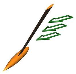 Similarly, if we imagine the combined fin and rudder area is perhaps 0.05 sq.m, with the appendages developing a coefficient of lift CL
of around 0.2, then total appendage lift is about
Similarly, if we imagine the combined fin and rudder area is perhaps 0.05 sq.m, with the appendages developing a coefficient of lift CL
of around 0.2, then total appendage lift is about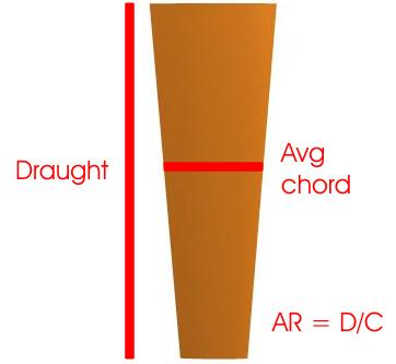 The coefficient of induced drag is given by
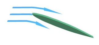 The aerofoil section affects performance of the fin due to the way the fin develops lift and drag with leeway. The familiar NACA four-digit
sections have good lift to leeway curves, but tend to generate more drag than a modern section would produce. The key to a modern section is
its drag bucket. To understand this, we need to understand how an aerofoil section works.
The aerofoil section affects performance of the fin due to the way the fin develops lift and drag with leeway. The familiar NACA four-digit
sections have good lift to leeway curves, but tend to generate more drag than a modern section would produce. The key to a modern section is
its drag bucket. To understand this, we need to understand how an aerofoil section works.