|
Balance, Part II
by Lester Gilbert
We started our consideration of Balance in the “Part I”
article of Issue 187 and found that changes of in- and out-wedge areas for a
heeled hull had anecdotal support for predicting balance in practice, but there
was no rigorous evidence. In this final article we’ll look at the “standard”
theory of how the centers of lateral hull resistance (CLR) and aerodynamic
effort (CE) should be arranged, and we’ll finally review an experiment that
shows why these theories are inadequate.
Theory of sailing
We know that the sails are like airplane wings, giving lift
that drives the boat forward and heels it over. The aerodynamic sail force is
considered to act through the CE (center of effort) of the sail plan, roughly
one third of mast height above deck and (depending on the ratio of foresail to
mainsail area) somewhat forward of the mast.
We know that the keel, the rudder, and to some extent the
hull are like wings that, using the boat’s leeway, resist the side force of the
rig moving the boat sideways. The hydrodynamic hull force is considered to act
through the CLR (center of lateral resistance), which (very roughly) for an IOM
is 40 percent of draft and some distance aft of the fin quarter chord.
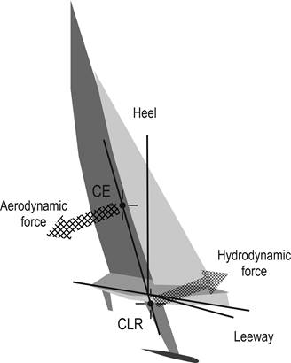
Our discussion of balance and helm is focused on yaw and
hence only on the forces acting in the horizontal plane—in plan view—and will
ignore the forces acting in the vertical plane, involved with the righting
moment and heel lever. When the boat is sailing in equilibrium, the aerodynamic
and hydrodynamic forces are in balance. In order to be in balance, the
aerodynamic force acting through the CE must align, in plan view, exactly with
the hydrodynamic force acting through the CLR, as illustrated in Figure
2 for a boat which is sailing nicely
heeled at, say, 25degrees. It is clear from Figure
1 that, in the vertical plane, the
aerodynamic and hydrodynamic are completely offset and form a heeling couple,
opposed by the righting moment of the hull and ballast.
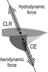
Figure 2.
Aligned CE and CLR positions in heeled equilibrium.
Although we may not know it, when we trim the boat to sail
the course we want, sailing theory tells us that we are arranging the position
of the CE (raking the mast, twisting the sails, setting the sheeting angles) and
the CLR (setting the rudder angle) so that the forces acting through them “line
up and are equal.”
The estimate we might make about the position of the CE is
usually quite a good one (but it’s still an estimate), because we have very good
theories of flight, which give good results for aerodynamic forces. It remains
an estimate because we cannot calculate, exactly, how much the CE moves, given a
change in the foresail twist measured at the upper batten from, say, 5 to 10
degrees. We would have a good chance of calculating it if the foresail was a
hard wing sail, but it is soft, thin, and takes up shape in different ways
depending on (for example) wind speed, construction, and age.
Mast-to-fin
“lead”
In practice, everyone knows that the mast must be positioned
forward of the keel. This is called “lead” [think "lead the dog towards the
rabbit", not "cast the bulb in lead"]. This ensures that the CE aligns with the
CLR (Figure 2), because the CE is
somewhat aft of the mast. For a Bermuda rig, builders and sailors know the mast
must be stepped somewhere between 3 and 10 percent LWL forward of the fin
leading edge (and as low as 1.5 percent for an IOM).
The guess we might make about the position of the CLR is just
that, a guess. If we do not have access to powerful Computational Fluid Dynamics
(CFD) and Velocity Prediction Program (VPP) software and a super-computer, we
are left with the modeler’s state of the art, cutting out the profile view of
the underwater hull shape and balancing it on a pin. Can we turn our guess into
an estimate, using software to simulate the pressure distribution around a hull,
keel, and rudder assembly, towing tank tests to calibrate our simulations, and
further fudge-factor calculations to correct for wave drag? Claughton, et al
(2013) say we can, and we’ll look at their claims shortly, but currently no one
can calculate the actual lead that properly trims a design until it is on the
water and sailed.
In a gust
This theory of sailing tells us that, when the boat luffs up
in a gust and bears away in a lull, it must be because the CLR has moved so that
the hydrodynamic force no longer lines up
with and is equal to the aerodynamic force. You will probably be familiar
with the various intricate vector diagrams that illustrate the forces and
moments of a heeled sailing boat and the effects of movement of the CLR.
Figure 3 shows the
standard theory of forces when a gust hits. The boat heels to, say, 45 degrees
and the additional heel moves the CE further abeam and thus aft of the line
where it balances the CLR. The forces are now offset, resulting in a yaw moment
to weather. Correcting this requires weather helm, and it is said that the helm
moves the CLR aft so that the hydrodynamic force acting through it, again, lines
up with the aerodynamic force acting through the new CE.
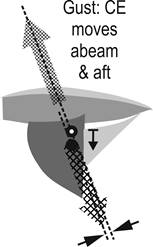
Figure 3.
Further heeling in a gust moves the CE abeam and effectively
aft.
In a lull
In a lull, the reduced heel of, say, 5 degrees moves the CE
inboard and thus forward of the line where it balances the CLR. The forces are
now offset, resulting in a yaw moment to lee. Correcting this requires lee helm,
and it is said that the helm moves the CLR forward so that the hydrodynamic
force acting through it, again, lines up with the aerodynamic force acting
through the new CE.
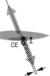
Figure
4. Reduced heel in a lull
moves the CE inboard and effectively forward.
But theorists eventually admit their apparently rigorous
analysis completely fails to predict balance characteristics in practice. The
theory of sailing, probably best outlined in Garrett (1996) for the emphasis
placed on the balance between aero and hydro forces, is descriptive but not
predictive. What’s wrong?
Quiz
Take your yacht. Take away the sails, remove the mast, and
all rigging. Take away the keel and the rudder but place the ballast inside the
hull so it doesn’t tip over. You are left with the canoe body.
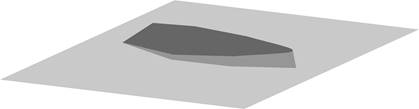
Figure 5.
Canoe body heeled at 15 degrees with internal ballast.
Impart some forward motion to the canoe body, so she moves
straight ahead without leeway. What is her heading and course? Now, move the
ballast to one side so the canoe body heels over at, say, 15 degrees
(illustrated in Figure 5), and push her
off again. How has her heading and course changed, if at all?
Pierre Raynaud’s
experiment
Pierre answered the quiz with an experiment. To give his IOM
hull some drive, he mounted an electric flight motor and aero propeller low on a
stub mast, and an offset container with some ballast at the top of the mast. The
arrangement is shown in Figure 6, where
the de-rigged boat is heeled to port.
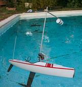
Figure 6.
Pierre Raynaud’s IOM in the swimming pool.
The hull was heeled at 10, 20, and 30 degrees and driven
along at about 1 m/s, similar to the speed that might be seen in an IOM
close-hauled in a 4 m/s breeze. The boat luffed up, that is, she turned away
from her direction of heel just as she would if she were carrying sail and were
caught in a gust. This is illustrated in Figure
7, where we see that the luff trajectory was increasingly tight
(decreasing radius) with increased heel. (Note that the fin and rudder were in
place, but this was for convenience; we have towed a hull in a towing tank
without fin and rudder and have reproduced these findings.)
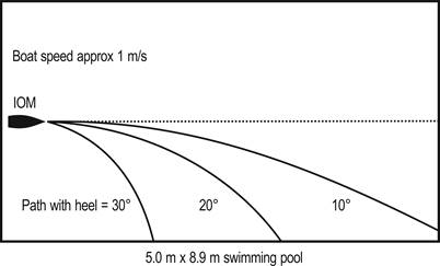
Figure 7.
Heeled canoe body luffing paths for various angles of heel.
Did you guess that when you answered the quiz? It turns out
that almost anything that could be considered a hull will, when heeled, turn up
towards her weather side. Experienced
dinghy sailors know this, as do most canoeists, kayakers, and motorized
small-craft sailors. This inherent behavior of a heeled hull shape is
unaccounted for, however, in the current “standard” theory of sailing when the
hull heels due to the action of the wind while sailing. In particular, there
seems little prospect of calculating the magnitude of the luffing moment from
the shape of the hull or the hull sections. We need to look elsewhere.
Airfoil pitching
moment
It is known that a heeled hull provides some contribution to
hydrodynamic lift in proportion to its leeway. We can see that the heeled
waterplane has an airfoil section, and in some sense the hull is a very
short–span, blunt wing. As well as generating lift, a wing has a pitching
moment. What is interesting is that, as long as the wing is moving through a
fluid, at zero lift, the wing still has a substantial pitching moment. This is
illustrated in Figure 8, where the high
pressure at the bow, coupled with the low pressure to weather, shows how the
luffing (pitching) moment occurs. The heeled hull
follows its camber line curve, and
perhaps this is the luffing moment we saw in Pierre’s experiment.
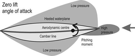
Figure 8.
Luffing (pitch) moment generated by a heeled hull which
otherwise shows no lift component.
Conclusions
A heeled hull when underway luffs strongly to weather. When
rigged, [mast] lead is required so the offset aerodynamic force can provide an
opposing torque and keep the boat on course. Helm doesn’t
move the CLR; it provides the
adjusting moments needed to hold course. This is illustrated in Figure
9.
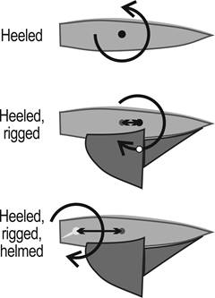
Figure 9.
Heeled, rigged, and helmed—it is all about moments.
No one knows how to calculate the hull’s luffing moment from
the lines plan or any other drawing board element. Well, perhaps this
conclusion might not be true; perhaps
those who know might not be telling us.
Following on from the 1903 flights at Kittyhawk, the theory
of flight was sewn up by the mid-1920s. The only new theories appeared with
supersonic flight in the late 1940s. Today any airplane can be designed, and
it’ll fly to within 1 percent of its predicted performance. But we still can’t
determine, from the drawing board, the balanced mast position to within 10
percent LWL, though an experienced designer with a history of practical
experience with a family of past hull lines for a particular class should be
able to do better, within 2 percent, say.
Perhaps those using CFD to look at the forces and moments on
a heeled, yawed, and moving hull, appendages, and rigs are able to make more
exact calculations, and we might finally be able to position a rig on a hull
with some confidence about the resulting balance.
References
Claughton, A, Pemberton, R, & Prince, M (2013).
Hull-Sailplan balance, “lead” for the
21st Century. (www.hiswasymposium.com/assets/files/pdf/2012/Claughton%20HISWA%202013.pdf)
Garrett, R (1996). The
Symmetry of Sailing: The Physics of Sailing for Yachtsmen. Sheridan House.
Acknowedgements
Graham Bantock gave valuable comments on an earlier draft.
The remaining errors are all mine.
|
.htm_cmp_lghome010_bnr.gif)