|
Balance, Part I
by Lester Gilbert
We touched on balance in the “Weather Helm” article of
Model Yachting Issue 182 and thought
that the topic deserved an article all by itself. In fact, it’ll run to two
articles—Part I here, and Part II in the next Issue—because there is a lot to
talk about.
To start, we need to improve the definition of
balance that we used. Most radio
sailors think a balanced boat is one that sails her course
hands off, but that is really a
definition of trim and not balance.
We make this distinction now, because we saw that a well-trimmed boat could (and
probably should) have some amount of weather helm, and so it must always be
sailed hands on, and we reserve the idea of balance for a boat that continues to
sail her course with minimal heading change when a gust or a lull comes by. The
idea of the boat behaving herself when in equilibrium we’ll call
trim, and
balance is when the boat behaves
herself during a dynamic change of wind speed.
A useful and accessible overview of theories of balance is
given by Satterthwaite (1960), and not a lot has changed in the nearly 60 years
since. We can compare this with the fact that, following the Flyer’s launch in
1903, the theory of flight was pretty much complete by the mid-1920s. The only
new theories turned up with supersonic flight in the late 1940s. Today any
airplane can be designed and it’ll fly to within one percent of its predicted
performance. But we still can’t predict a mast position to within 10 percent of
LWL and haven’t been able to do so in the, oh, 45,000 years
since we’ve known about sailing boats.
Satterthwaite finds there are only three theories of
balance—the theory of balanced sections
since the 1700s, Admiral Turner’s
metacentric shelf since the 1920s, and Heckstall-Smith’s
master diagonal circa 1930. We’ll
focus on balanced sections, since Satterthwaite tells us that this is,
essentially, a version of Turner’s metacentric shelf on the one hand, and on the
other hand that not too many designers use master diagonals. I think you’ll
recognize balanced sections as the theory of the in-wedge and the out-wedge as
the boat heels, and we compare the areas (and by implication the volumes) of the
immersed with the exposed sections.
In- and
out-wedges
We take the sections of the upright hull, strike a heeled
waterline, and compare the areas of the in-wedges with the out-wedges at each
section. A section lines plan of a narrow-transom hull is illustrated in Figure
1, with an upright waterline and an
estimated waterline for 15 degrees of heel defining the wedges.
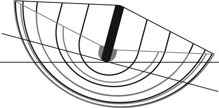
Figure 1.
Section lines with upright and heeled waterlines.
The lines of the hull in Figure
1 show sections that are based on
circular arcs and that would be appropriate for a class such as the IOM, where
both the stem and the transom just touch the water. (I have a spreadsheet
that allows you to draw circular arc sections in a variety of ways and that
provides some of the graphs and calculations mentioned in this article.)
For each section, we calculate and compare the areas of the
in-wedges and out-wedges. This is illustrated in Figure
2, where we consider section 1 at the
bows, midsection 5, and section 9 towards the stern.
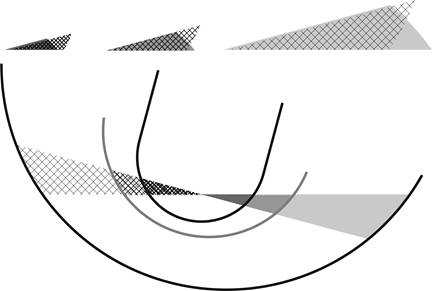
Figure 2.
Comparison of in- and out-wedges, narrow-transom hull.
We can see in Figure 2
that the midsections immerse more volume on heeling (the shaded midsection
in-wedge is larger in area than the crosshatched, midsection out-wedge), while
both fore and aft sections immerse less volume (shaded in-wedges larger in area
than crosshatched out-wedges). Let’s take essentially the same lines, but now
have a wide-transom hull. The comparison of the in- and out-wedges is shown in
Figure 3.
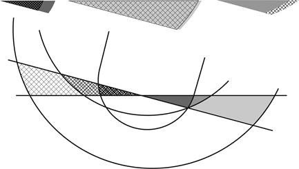
Figure 3.
Comparison of in- and out-wedges, wide-transom hull.
In this case, we see a somewhat different outcome in Figure
3, such that the fore and midsections
immerse more volume on heeling (the shaded in-wedges are larger in area than the
crosshatched out-wedges), while the aft sections immerse less volume.
Curve of wedge
area changes
We can now draw a graph of the changes in immersion, section
by section, and the results are illustrated in Figure
4 and Figure
5 for the narrow- and wide-transom hulls,
respectively.
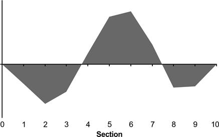
Figure 4.
Curve of wedge area changes, narrow-transom hull.
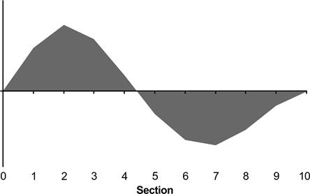
Figure 5.
Curve of wedge area changes, wide-transom hull.
The COWAC (curve of wedge area changes) graphs of Figure
4 and Figure
5 are used to suggest which boats are
likely to be better balanced, and which boats are likely to be badly balanced.
As is customary in these articles, before proceeding, let’s have a quick
quiz—which hull would the COWAC graph say is better balanced?
Better balanced, please, not
better trimmed. Don’t carry on
reading! Pause and reflect…
Just before we provide an answer, you may have a question of
your own, and it probably runs like this: “I’m happy with the upright waterline,
but where, exactly, shall we place the heeled waterline? Its placement will make
a profound difference to the COWAC graph, because in one place it could show the
aft sections immersing more, while in another place it could show the opposite.”
This is an excellent question, and it raises at least three
issues. Taking the lines of the Figure 1
hull, if it were an IOM, it turns out that it would rise approximately 5.5 mm
when heeled at 30 degrees on a perfectly flat water surface—the increased
immersion that occurs midships necessarily means less immersion elsewhere to
maintain the same displacement.
The first issue, of course, is that the water surface does
not remain perfectly flat when the boat is heeled; if nothing else, the boat
must be moving in a reasonable breeze to heel at 30 degrees, and so the hull
will sit in its self-generated Froude wave, such that each section will have its
own unique waterline depending upon the local wave amplitude.
The second issue is that, while the hull as a whole might
rise a little on heeling, we would not expect it to continue sailing without any
pitch change. We would probably expect the hull to pitch bow-down, while
remembering there are some hulls that are known to pitch stern-down and lift
their bow when heeled, and again each section will have its own waterline.
The third issue is that, while a narrow-transom hull would
show less yaw in the same way as a heeling cylinder, a wide-transom hull will
yaw in the same way as a heeling cone. We can call this
slew, and it is illustrated in Figure
3 where, imagining the hull is sailing
towards you with the wind on her starboard side, you can see the bow-, mid-, and
aft-sections are offset. The angle of slew of our wide-transom design is
estimated at around 2.5 degrees at 30 degrees heel, and so, again, each section
will have its own waterline.
We are going to ignore these complications for this analysis
and have our hull sailing upon a flat surface with no pitch change. We will
include slew, but because our lines are arcs of circles, slew has no effect upon
the calculations. If you wish to get serious, your naval architecture software
will generate the right waterlines and COWAC graphs for you.
Now, what did you think about the COWAC graphs? It is
suggested that a graph that looks like Figure 4
illustrates a boat that will be better balanced, while Figure
5 illustrates a boat that is likely to be
badly balanced. Boebert (2007) provides a thorough discussion of these ideas in
his paper on model yacht balance, where you will notice that the COWAC graph is
the same as the moment graph used in Turner’s metacentric shelf analysis. The
metacentric shelf is the idea that a
COWAC graph is balanced on a shelf edge, and will tend to stay balanced if the
COWAC curve is balanced between the
in- and out-wedge area changes, as illustrated in Figure
6.
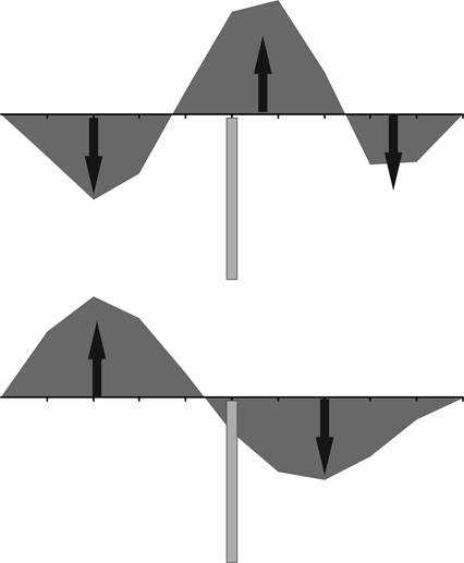
Figure 6.
Curve of wedge-area changes balanced on the “metacentric shelf.”
Conclusions so far
There are anecdotal claims of correlation between a COWAC
graph for a hull and its balance in practice when sailing, but there is no
rigorous evidence. The COWAC graph illustrates static characteristics of the
hull, but balance is a dynamic matter. It is not surprising that there cannot be
any rigorous demonstration of cause and effect.
We know that, in practice, a boat is trimmed by moving the
position of the mast. Part II of this article will start by looking at theories
of how the centers of lateral hull resistance (CLR) and aerodynamic effort (CE)
should be arranged. By way of a spoiler alert, we’ll find out how these theories
are just as inadequate as the theories of balance we’ve looked at here.
Fortunately, Part II will explain why all current theories of balance are
faulty.
References
Boebert, E, (2007).
“That Peculiar Property:” Model Yachting and the Analysis of Balance in Sailing
Hulls. 18th Chesapeake Sailing Yacht Symposium, downloaded from
(www.sname.org/HigherLogic/System/DownloadDocumentFile.ashx?DocumentFileKey=9818a2eb-c8e9-45ee-bd9d-5029f13d432c)
on 20 October 2016.
Charles Satterthwaite (1960).
Sailing Theory. AYRS. Downloaded from
(www.ayrs.org/repository/AYRS031.pdf) on 20 October 2016.
Acknowedgements
Graham Bantock gave valuable comments on an earlier draft.
The errors are all mine.
Maritime
History,
Wikipedia. https://en.wikipedia.org/wiki/Maritime_history
Hull
Design With Arcs,
http://www.onemetre.net/Design/Design/Design.htm
|
.htm_cmp_lghome010_bnr.gif)