|
Scale Models
Lester Gilbert
Constructing a model yacht involves two broad issues, one
concerning proportions and the other concerning sailing performance.
This article considers proportions when scaling length, area,
displacement, and speed, and sailing performance related to stability and
pointing.
“Ranger 1937”
scaled
Let’s make a one metre model of the 1937 J boat
Ranger at 1:40 scale, that is, a
scale factor (f) of 0.025, 25 mm in
1000 mm, approximately 1” in 3’.
The resulting outline and simple sail plan is illustrated in
Figure 1.
This will not measure as an AMYA J Class boat because those boats scale
at 1:16, a factor of 0.0625, 2¼” in 3’, but the principles of their scaling are
the same.
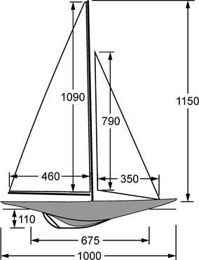
Figure
1.
Profile view of model
Ranger with a simple sail plan,
dimensions in millimetres.
Wikipedia tells us
Ranger’s LOA was 41 m with LWL of 26.5 m and draught of 4.6 m.
These and other length dimensions scale linearly in
f yielding a model with LOA of
1000 mm, LWL 675 mm, and draught 110 mm.
Her 46 m mast scales to 1150 mm, and her 6.35 m maximum beam scales to
160 mm.
Ranger’s
sail area is listed at 700 square metres, so the model’s sail area would scale
as f², 1:1,600 or 0.000625, yielding
0.44 m². For simplicity we’ll
construct the model with a non-overlapping foresail giving a sail area of
0.39 m².
Ranger’s
displacement is listed as 166 tons or around 169,000 kg.
Volume scales as f³, 1:64,000
or 0.0000156, yielding a model which displaces around 2.6 kg.
While we have estimated our model will weigh 2.6 kg when floating on her
waterline, we will have to make an informed guess how much lead weight we can
put at the bottom of the keel. The
hull and rig of a lightly-built two-channel one metre boat is around 1.5 kg, so
with luck we can put 1.1 kg into the bottom of the keel.
Froude and top speed
There is the question of the model’s sailing speed.
Full size Ranger could
probably reach 12 kt, 6.2 m/s, or 14 mph in a good breeze and would be well
heeled. If this is scaled linearly in
f, the “equivalent” model speed would
be 0.15 m/s or 0.35 mph. That would
be a very slow model and at such a drifting speed it would show little heel.
The model clearly can sail faster, and here we see the first indication
that the dynamics of a model are different from a simple linear scaling of the
full-size boat.
Wikipedia tells us that Froude found that the size
(wavelength and trough depth) of the wave pattern generated by a hull in motion
increased in proportion to the square root of its LWL.
As a first approximation, we take the size of the wave generated by the
hull as the limit to its top speed (for a heavy displacement hull such as
Ranger).
We therefore scale full size
Ranger’s top speed by the square root
of the scale factor,
√f = 0.16,
to estimate the top speed of model Ranger
as 1.9 kt, 1 m/s, or 2.2 mph. That
is far more realistic.Aside on Froude
number
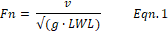
The top speed of a heavy displacement hull is usually said to
be found when its Froude number, Fn, is around 0.4.
Equation 1 defines Fn as the “speed to length” ratio (speed, v, to square
root of length, LWL, actually) normalized by the gravitational constant, g.
Sailing forces
To see how our model will probably sail, we need to estimate
the forces generated by the sails on the one hand and by the keel on the other.
Lift force is given by Equation 2, where we have a lifting
body like a rig or fin of a certain area S moving through a fluid with density D
at a velocity V and at a coefficient of lift Cl.

We imagine our model sailing in an apparent wind of 2.5 m/s,
5 kt or 5.7 mph with her sails of 0.39 m² sheeted to give a lift coefficient of
1.2. The density of air is
approximately 1.2 kg/m³, and so the sails are providing around 1.7 N, 0.18 kg,
of lift. We imagine that, in these
conditions, the boat is making her top speed of 1 m/s.
Keel area is approximately 0.018 m², the keel lift
coefficient at a likely angle of leeway is 0.2, the density of water is
1000 kg/m³, and so the lift generated by the keel is around 1.6 N, 0.17 kg.
We know that the rig forces must balance the hull and keel forces in any
boat which is sailing in equilibrium, and this very rough calculation shows that
the lift forces (at the least) of rig and keel are in broad agreement.
Aside on scale wind
speed
Our model seems to be sailing nicely at her top speed of
1 m/s in an apparent wind of 2.5 m/s.
Would full size Ranger
similarly sail at her top speed of 6.2 m/s in an apparent wind which is 2.5 m/s
scaled up by f?
This is around 100 m/s, so certainly not, that’s 224 mph.
Perhaps we should have scaled up by
√f, which would be 15.8 m/s, 35 mph,
31 kt? No,
Ranger would probably be back in the
harbour in such conditions. It is
likely that the wind speed would need to be no more than around 20 or 25 kt for
Vanderbilt to approve a training run.
This is another indication that the conditions
for sailing a model are different from a simple linear scaling of full-size.
Stability
So far, our scaled model of
Ranger is looking good.
We now have two important questions about our model.
Is she stable? Will she
point? Those of you with any
experience of a simple scaled model know that the answers will not be so
promising.
We can estimate stability by calculating the righting moment
of the ballast, and seeing how that compares with the heeling moment of the
sails.
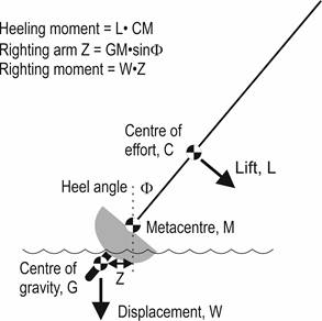
Figure 2. Abstract view of
boat with displacement W heeled at angle Φ due to sail lift L.
We imagine the boat heeled at an angle, Φ, being pushed over
by the sails exerting a lifting force L and being righted by her displacement,
W, of 2.5 kg.. The metacenter is
that point M directly above the centre of buoyancy (CB) which intersects the
couple of heeling and righting forces.
The metacentre moves as the boat heels, following the movement of the CB.
This movement will be smaller for a hull with narrow beam, and larger for
a hull with wider beam. As a rough
estimate, using a triangular section hull, the height of M above the CB is per
Equation 3 for a given beam at the waterline and an immersed depth.

For our model, we imagine the “triangular” section of the
canoe body below the waterline to have a beam of 100 mm and an immersion of
30 mm, giving the height of M above the CB as approximately 56 mm.
We next imagine that the CB is 1/3 of the immersion below the waterline,
10 mm, suggesting that the height of M above the waterline is 46 mm.
Finally, we imagine that the deck is around 40 mm above the waterline, so
M is around 6 mm above deck. It is
common for the metacenter to be slightly above deck level, and for our following
calculations we will ignore the 6 mm, conveniently considering M to be at deck
level, around 40 mm above the waterline.
The sail lift force, L, acts through the centre of effort of
the sails, C, with an arm given by the distance between C and M.
Notice that the sail generates lift no matter the angle of heel, since it
is always sailing forward in its apparent wind.
The heeling moment is thus given by L•CM.
For a triangular sailplan, we can
estimate the centre of effort to be approximately 33% of mast height, around
0.41 m above deck level and hence above M.
We’ve estimated L to be 0.18 kg, and so the heeling moment is around
74 kg-mm.
The boat’s displacement, W, acts through the centre of
gravity of the boat, G, with an arm, Z, given by the horizontal distance between
M and G. When the boat is laid
flat, the arm Z = the distance MG for maximum righting moment, and when the boat
is upright, arm Z = 0 and there is no righting moment.
Hence we can see that the righting arm Z = MG Sin Φ, and the righting
moment is Z•W. (Recall that Sin 0°
is 0, and Sin 90° is 1.)
Calculating the centre of gravity of model
Ranger is not very easy on paper (but
can be established very quickly in the workshop).
We have estimated a 1.5 kg build of hull and rig, and 1.1 kg of lead in
the quite short keel, and so estimate G to be around 35 mm below deck level,
suggesting MG is 35 mm and the righting moment, W•Z, is 2.5•35•Sin Φ kg-mm, that
is, 87.5•Sin Φ kg-mm.
The angle of heel where the righting moment equals the
heeling moment is where 87.5•Sin Φ = 74, hence Sin Φ = 74/87.5 = 0.85, so Φ =
ArcSin (0.85), that is around 58°.
The model is tender!
We’d prefer to have her heeled at 30° in these conditions, not nearly
60°, and to do that we’d need a righting moment of 148 kg-mm, that is, where
Sin 30° = 0.5 = 74/148. This needs
the centre of gravity G to drop to something like 59 mm below M (148/2.5).
This movement of G by 24 mm from its estimated 35 mm below deck level
suggests the 1.1 kg ballast in turn needs to move deeper in the proportion
1.5:1.1 of 24 mm, that is, by 33 mm. The
aggregate movement of 24 + 33 = 57 mm is the suggested increase in draught of
57 mm to give a new value of around 167 mm.
The underwater profile would no longer look quite like an exact scale
model on shore, but in the water would look nicely authentic!
The extreme lack of stiffness of a scaled model is why the
AMYA J Class Rules permit an extra 2” of draught.
Aside on ballast
ratio
The ballast ratio is a very useful parameter when comparing
two boats of the same class. Full
size Ranger’s ballast ratio is
110 tons keel to 166 tons displacement, a ratio of 66% and probably best in
class. Model
Ranger’s ratio is 1.1 kg to 2.6 kg,
43%. The ratio of a racing model
yacht such as an IOM is 2.5 kg to 4 kg, 63%, and that is a little on the low
side compared to a Marblehead or Ten Rater.
A carefully built A Class can achieve a remarkable 80%.
The relatively modest ballast ratio of model
Ranger might be thought to be the
primary reason for her lack of stability.
If we decided to build the model with a ratio of, say, 66% to match full
size, it turns out that the hull, rig, and radio gear would need to weigh no
more than 0.88 kg., This is
currently infeasible even with the lightest carbon fibre and sailcloth materials
and the most scrupulous attention to construction.
If a ratio of 66% was somehow achieved, it is useful to note
that the model would then be acceptably stable, carrying her 1.72 kg keel at the
scale draught of 110 mm with G around 59 mm below M as required.
Pointing
The “course theorem” explains a boat’s ability to point into
the wind, outlined on my web site at
Course Theorem.
In short, we add up the drag angles of the aero and hydro components of
the boat to get ß, its best close-hauled sailing angle to the apparent wind.
The drag angle of the aero component is given by the angle
whose tangent is the ratio of the lifting force of the sails to the drag force
of sails, rig, and hull above the water. Similarly the drag angle of the hydro
component is given by the angle whose tangent is the ratio of the lifting force
of the keel, hull, and rudder to their drag forces.
A very simple approach is to calculate the drag angles of the
sails and the fin and see where that takes us, ignoring the parasitic drag from
wetted surfaces, component cross-sections, and waves.
This allows us to use coefficients of lift and drag to estimate drag
angles rather than needing to know the actual forces.
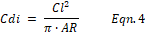
A sail or a fin generates induced drag whenever it generates
lift. The amount of induced drag is
in proportion to the square of the lift and to the inverse of the aspect ratio.
The coefficient of induced drag, Cdi, is calculated by Equation 4, given
the coefficient of lift, Cl, and the aspect ratio of the sail or fin, AR.
In yacht design, aspect ratio is estimated as the ratio of
the square of the span, b, of the sail or fin to its area, S, as in Equation 5.

The keel has a span of 0.11 m and an area of 0.018 m², giving
a keel AR of 0.67. In the case of
the sails, their combined area of 0.39 m² has a span of 1.09, giving a sail plan
AR of around 3. This is an
underestimate of the effective AR of the sail plan because the sail area is made
up of two separate sails, but it is good enough for our simple purposes.
When the sails are providing a Cl of 1.2, Cdi is 0.15, the
ratio of these two coefficients is 0.13, and so the drag angle is ArcTan (0.13),
that is, 7°. Similarly, when the
keel is providing a Cl of 0.2, Cdi is 0.02, their ratio is 0.10, and the drag
angle is 6°. The sum of these two
drag angles is 13°. Just before we
exclaim at the possibility of our model of
Ranger sailing at 13° to the apparent
wind, we need to remember that all other sources of drag have been discounted.
These include: the skin drag of the rig, the drag of the spars and
rigging, the drag of the above-water hull, the skin drag of the hull, fin and
rudder, and the wave drag of the boat. Let’s
compare these drag angles to an IOM, which we know sails at around ß = 30° to
the apparent wind.
After running through these same calculations for an IOM, we
find the sum of the two drag angles to be 8.5°.
This suggests that the ignored drag contributes a drag angle of 30 – 8.5
= 21.5°. If the ignored drag in the
model Ranger is similar to an IOM,
then ß for model Ranger is around
35°. Experience suggests this is
very likely a good ballpark figure.
We can improve model
Ranger’s ability to point by changing her keel to a fin and bulb, with a
draught of at least 170 mm as suggested earlier for improved stability.
Such a fin would have AR = 1.6 and have a drag angle around 3°, half that
of the keel it replaces which we estimated at 6°.
ß for a model Ranger with an
efficient fin would be around 32°.
Aside on pointing
What would ‘scale’ pointing look like?
Would it or should it be the same as full size?
How well does full size Ranger
point? I’ve not been able to find
the answer to that question. If
exceptional build and exceptional materials can allow the model ballast ratio to
equal that of full size, the model would no longer be tender, but it would still
sail off the wind compared to a modern racer.
The only way around this is to increase draught to permit a modern
efficient fin; but perhaps that
would no longer be ‘scale’.Conclusions
on proportions and performance
A scaled model of a yacht is likely to work perfectly well
above the water, remembering to scale length by the scale factor
f, area by the square,
f², displacement by the cube,
f³, and top speed by the square root,
√f.
Below water, however, the scaled keel is likely to give a very tender
model which sails disappointingly off the wind.
The solution is straightforward.
If the model can be built relatively light, no additional displacement is
needed, instead the available ballast can be placed as a bulb on a fin for
efficiency, and we would suggest the fin has a span at least twice the scale
draught.
We have seen that the dynamics of a model are different from
a simple linear scaling of the full-size boat, particularly with regard to
stability and sailing on the wind.
In general, the laws of aero and hydrodynamics mean that a scale model will not,
and cannot, sail at ‘scale’ speed in a ‘scale’ wind with ‘scale’ heel.
But interestingly and perhaps surprisingly there is one dynamic ‘scale’
appearance that is realistic – the
wave patterns of both full size and scaled boats are identical.
Acknowledgement
Graham Bantock provided a number of comments and corrections.
All remaining errors are mine.
|
.htm_cmp_lghome010_bnr.gif)