|
Kinked Kicking Strap
by Lester Gilbert
I noticed a small bend in a kicking strap wire on an IOM
recently, and wondered if it might usefully act as a spring in a gust, easing
the clew, opening the leech, and de-powering the mainsail.
I’ve been looking for an excuse to explore finite element analysis (FEA),
so let’s run a computer program to simulate the stretch in the kicking strap.
Kicking strap model
I modelled a 316 stainless steel kicking strap in Solidworks,
and settled on four parameters to investigate – wire diameter, kink depth, kink
radius, and strap span, as illustrated in Figure
1.
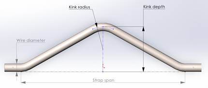
Figure
1.
Solidworks model of a kinked kicking strap showing the primary
parameters to be investigated.
(Not to scale.)
It took a few attempts to construct an appropriate constraint
on the strap so the Solidworks FEA could run its magic to determine how it
stretched under load. Eventually I
modelled a small opening in one end of the strap and set it as a fixed hinge,
while the other end took the load force.
Setting the starting values for the four parameters was
relatively straightforward, because most IOM straps are 1.5 mm diameter wire
around 150 mm in length, and bends are made using 5 mm diameter round jaw
pliers. The kink I saw on the World
Champion’s IOM seemed to have around 10 mm depth.
Then, setting a range of parameter values was a little more interesting.
I decided to opt for a geometric progression in each set of values, and a
brilliant little book, “Technical Formulae” by Gieck (2007 9th
Edition) gave me the necessary equations, r1 and r2 in the section on production
engineering. The resulting range of
rounded parameter values are listed in Figure
2.
|
Kink radius
(mm)
|
2.5*, 5,
10, 15, 30, 55
|
|
Span (mm)
|
80, 110,
150*, 210, 280
|
|
Kink depth
(mm)
|
2, 4, 6,
10*, 18, 30
|
|
Wire
diameter (mm)
|
From 1.0 to
2.0 in 0.1 steps (1.5*)
|
Figure
2.
Range of kicking strap model parameter values to be
investigated.
* Value held constant when not the parameter range being
investigated.
Finite element analysis
The most interesting values needed, however, were those for
the force experienced by a kicking strap while sailing.
We can calculate that an IOM mainsail beating at around 30° heel puts
around 15 N of tension into the leech, which translates into a tension in the
kicking strap of around 80 N (10 N is around 1 kg force, 4 N around 1 lb force).
I settled on an approximate geometric progression of forces applied to
the kicking strap as listed in Figure
3,
and used this list as input to the FEA to run against the model parameters.
|
Applied
force (N)
|
5, 10, 15,
25, 45, 80, 140, 245
|
Figure
3.
Range of forces applied to the kicking strap for FEA runs.
Figure 4
shows a screen shot of a FEA run, illustrating the predicted distortion in the
kicking strap and coloured according to the predicted stress concentrations.
It is interesting to observe the predicted shape of the stressed strap,
the curve introduced into the straight runs of wire either side of the kink, and
the stress concentration in the kink itself.
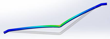
Figure
4.
Result of a Solidworks FEA of the kicking strap model,
superimposed on the static model.
(Not to scale.)
Predicted results
Each set of FEA runs varied one parameter at a time, holding
the other parameters constant. When
not varied, the constant parameter values were 1.5 mm diameter wire, 150 mm
strap span, 2.5 mm kink radius, and 10 mm kink depth.
Kink depth.
Predicted FEA increase in length (ease or
elongation) of the kicking strap for various kink depths is shown in the graph
of Figure 5.
The values for small depths are difficult to see in the graph because it
is scaled for the higher values for larger depths, so a table of the numerical
results is given as Figure
6.
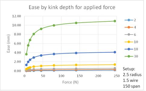
Figure
5.
Graph of predicted ease (elongation) of kicking strap for
various kink depths.
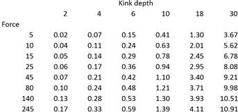
Figure
6.
Table of predicted ease (elongation) of kicking strap in mm for
various kink depths.
Strap ease for a kink depth of 10 is predicted to be around
0.4 mm under 5 N tension, rising to 1.2 mm at 80 N, and rising more slowly to
1.4 mm at 245 N when the rig is presumed to be completely overpowered.
Ease is much lower for smaller kink depths, and much higher for larger
kink depths.
A typical IOM kicking strap M4 adjustment wheel has a screw
thread pitch of 0.7 mm, so that one turn eases the strap by 0.7 mm, and in the
IOM world 3 turns or around 2.1 mm is a huge ease and would never find any
practical use. In this context, it
appears that a kink depth larger than 10 mm is therefore of little practical
value, and we can note that, at the highest applied force, a kink depth of 10 mm
provides the equivalent of 2 turns of an M4 kicking strap adjustment wheel.
Strap span.
For various strap spans, the predicted FEA
increase in length of the kicking strap is shown in the graph of
Figure 7.
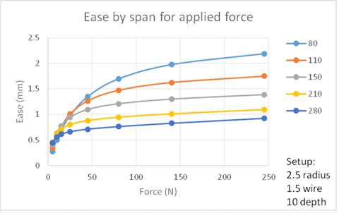
Figure
7.
Graph of predicted ease (elongation) of kicking strap for
various strap spans.
Interestingly, ease of shorter spans is predicted to be
greater than ease in longer spans when the strap is kinked.
The explanation is that the given kink
depth of 10 mm gives the short span relatively more opportunity to stretch out;
another way of saying this is that a given kink depth is relatively
smaller for longer span straps. The
ease of the 80 mm span strap gives the equivalent of up to 3 turns of an M4
adjustment wheel, while the ease of the 280 mm strap gives the equivalent of
just one turn.
We know that, in itself, a shorter strap permits greater
leverage of the boom by the sail leech force, giving more flex in the boom as a
gust hits and hence greater ease at the clew.
This result suggests that a kink is likely to be of more value in a
longer strap, since if placed in a short strap the combination of increased boom
flex and increased strap ease may well be excessive.
Wire diameter.
For various wire diameters, predicted FEA
increase in length of the kicking strap is shown in the graph of
Figure 8.
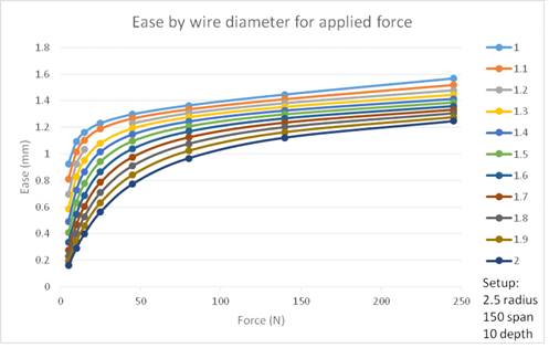
Figure
8.
Graph of predicted elongation of kicking strap for various wire
diameters.
It is interesting here to see that, largely, strap ease
reaches a maximum of between 1.2 mm and 1.5 mm under the highest applied forces
no matter the wire diameter, but at lighter forces the smaller diameters allow
much more ease. A thin 1.0 mm Ø
wire gives the equivalent of 1 turn of an M4 adjustment wheel almost immediately
any breeze appears (5 N force) while a stiff 2.0 mm Ø wire gives this 1 turn
equivalence when the boat is well heeled (80 N).
This suggests that ease is more progressive the larger the wire diameter
across the range of forces investigated.
Kink radius.
Finally, for various kink radii, predicted
FEA increase in length of the kicking strap is shown in the graph of
Figure 9.
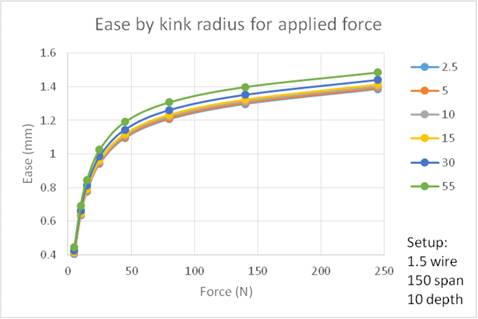
Figure
9.
Graph of predicted elongation of kicking strap for various kink
radii.
A kink radius of 55 mm, for instance, is simply a gently bent
length of wire to the desired depth, while a radius of 2.5 mm or 5 mm would be
formed over the jaws of pliers. It
is somewhat unexpected, certainly for me, to see that the kink radius makes only
a slight difference to the ease predicted, around 0.1 mm at most.
Discussion
Boom flex results in the mainsail clew easing as the breeze
strengthens. A separate article in
MY will consider boom rigidity and the effect of the positioning of the kicking
strap attachment point, but for the present it is estimated that 15 N leech
force at the clew of a typical 11 mm alloy IOM boom will cause the boom to flex
by up to 3 mm.
We have seen that, typically, a kinked kicking strap (1.5
wire, 10 kink depth, 2.5 kink radius, 150 span) is predicted to lengthen by
1.4 mm given an applied force of 80 N, which is what is generated by 15N at the
mainsail leech of a well-heeled IOM.
My spreadsheet at Calculating
Twist tells us that, with ‘typical geometry’, when the kicking strap eases
by around 0.5 mm, that is, with approximately 2/3rds of a turn of the kicking
strap adjustment wheel, the clew is raised by around 3.3 mm.
An ease of 1.4 mm would give more than triple the rise at the clew.
The spreadsheet tells us that, with ‘typical geometry’, a
clew rise of around 3.3 mm (kicking strap ease of 0.5 mm) takes the twist at the
top batten of the main from, say, a tight 1.8° to a very loose 22°.
This corresponds to the ‘full range’ of twist adjustment that might be
needed on an IOM mainsail.
Summary
For an IOM heeled at 30° and ‘typical rig geometry’:
·
From an initial 1.8° upper
batten sail twist, a clew rise of 3.3 mm takes this to 22°.
·
A range of sail twist between
1.8° and 22° at the upper batten is as much as might be needed when sailing.
·
Approximately 2/3rds of a turn
of the M4 kicking strap adjustment wheel gives a clew rise of 3.3 mm.
·
The flex in a typical boom
would in itself raise the clew by up to 3 mm.
·
A kinked typical kicking strap
would in itself raise the clew by around 3.3 mm.
Conclusions
A deep dive using FEA into the predicted extension of a
kinked kicking strap tells us this might only be of use when the breeze gets up,
or a gust hits, if our rig uses an exceptionally rigid boom with negligible
flex.
If we do have an exceptionally rigid boom, then a kink depth
of 5 mm or so (1.5 wire, 150 span, any kink radius) in the kicking strap might
have some benefit when a gust hits.
Otherwise, adjusting the leverage, that is, the attachment point of the strap to
the boom, gives the range of clew ease that might be needed.
Acknowledgements
Graham Bantock provided the estimates of leech tension used
in this article, as well as comments based on 50 years of top-level experience.
As usual, all the errors are mine.
|
.htm_cmp_lghome010_bnr.gif)