|
Adjustable Spreaders
by Lester Gilbert
The perfect spreader – rigid, locked on the mast, locked to
the shrouds, and with adjustable sweep – is an obsession I’ve had for some
years. In that time I’ve prototyped
43 designs (at last count!), some designs in several versions, and with some
versions themselves in a variety of revisions.
I manufactured a limited edition batch of “Design 43 Mark 10 Revision C”
variable sweep spreaders, and drafted a “user manual” at
Adjustable spreaders v43.
When a spreader is locked and rigidly in pace, the lateral
stiffness of the mast and shrouds combination is effectively four times higher
than with spreaders which pivot on the mast or where the shrouds move through
the arms.
The stiffness of a thin wall tube is proportionate to the
third power of its radius, Eqn. 1:

A tube mast of, say 11 mm diameter will have stiffness
equivalent to a 17.5 mm diameter mast when its stiffness is increased four-fold
(other things being equal). That’s
quite a nice improvement in stiffness (Eqn. 2).
Figure 1
and Figure 2
illustrate 20 of the better designs I came up with over the years, starting
around 1998 for design #2 up to 2016 for design #43.
I’ve further developed #43 into my current design #52 which is a 3D
printed version as featured in Model Yachting issue #199.
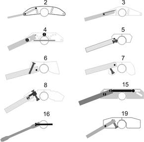
Figure
1.
A sample of earlier adjustable spreader designs.
Design #16 was probably the most successful of these earlier
works, and was used on my IOMs for some years.
The arms were 6 mm aluminium knitting needles, turned down to 4 mm in the
centre. Their sweep V was adjusted
by unclamping the shrouds, moving the arms up or down as needed, and
re-clamping. Their advantage of
exceptional simplicity was eventually overshadowed by their disadvantage.
Their effective arm length decreased as the arms were rotated, leading to
lower shroud tension which then required compensation.
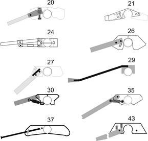
Figure
2.
A sample of later adjustable spreader designs.
Design #24 was suited to a larger boat, and worked well on my
A Class for many years. The arms
were 6 mm aluminium knitting needles, with aluminium bottle screw adjusters from
the Graupner Micro Magic.
Design #43 is my current design.
The mast fitting (arm carrier) is relatively modest in size and hence in
windage, and changing to longer or shorter arms is relatively straightforward.
Associated with designs for sweep V adjustment are designs for locking the wire
shroud to the end of the spreader arm in order to achieve the promised increase
in effective lateral mast stiffness.
The design space is a little smaller, and most of the designs are
illustrated in
Figure 3.
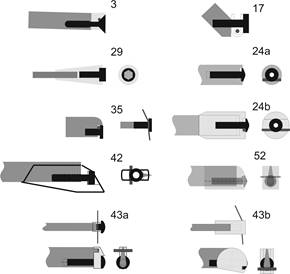
Figure 3.
A sample of arm cap designs.
The most successful method of clamping the shroud to the arm
was design #35. Here, the SAILSetc
aerofoil spreader bar is notched and rounded, and tapped to M2 to accept a
button head M2 12 mm clamping screw.
Because the bar sides expand slightly when being tapped, the bar needs to
be held lightly in a vice. Not too
firm, otherwise the bar will compress and the tap will break.
|
.htm_cmp_lghome010_bnr.gif)