|
3D Spreaders
by Lester Gilbert
I settled on a design of an adjustable sweep spreader (Adjustable
spreaders v43) that turned out to be rather time-consuming to manufacture,
so I revised it for 3D printing. A
trial design, #51, was printed in PLA Plus from eSun.
I’ve found PLA Plus to be a rather nice filament, recommended by Selwyn
Holland, very easy to print but significantly stronger than PLA, and great for
prototyping. The same design
printed well in ABS, Nylon, n-Vent, and ASA, but did not seem to be
significantly better in strength.
The problem I found rather quickly was that the prototype
fitting wasn’t able to hold the adjusting grub screws for longer than a regatta
or two. This was not surprising
since threaded holes in a thermoplastic are always going to be fragile.
The design allows for a 35 degree range of sweep as shown in
Figure 1,
taking around 4 turns of the grub screw.
Although the grub screws are 5 mm long, they typically engage only four
or so threads when bearing against the spreader arms.
Turning them in and out as the wind built and died to give me the mast
bend I wanted soon destroyed the threads.
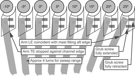
Figure
1.
Range of adjustable sweep.
Design #52 (version 4) allowed all threaded holes to be
provided by heat set threaded brass inserts.
The 3D design is illustrated in Figure 2,
where the oversize holes are easily seen.
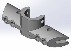
Figure
2.
3D design #52 with provision for heat set threaded brass
inserts.
There are three challenges with heat set inserts.
The first is getting an insert positioned in the right place.
When nice and hot and pushed into plastic, they’ll melt right in wherever
you start and no matter your intended pilot opening to guide them into place.
So some mechanism to position and then hold the insert and its setting
tool is needed.
The second challenge is providing some method of keeping the
insert aligned during insertion. It
is one thing to position the insert correctly at the start, but another to keep
it straight and true while it is being slowly driven into the plastic.
The third challenge is ensuring the correct temperature of the insert before
pushing it into place. While the 3D
printer extruder might have heated the filament to 220
°C to deposit it, you want a lower temperature for the
insert, perhaps 20
°C cooler at around 200
°C in this case.
A good temperature is required, of course, so the displaced plastic flows
well around the insert and, when it cools, holds it in place, but too high a
temperature and the insert could drop right through the item under its own
weight. So some temperature control
of the setting tool is required.
These challenges are met with a variable temperature,
exchangeable tip, soldering or hobby iron mounted in a press.
The particular temperature range you will need is from 150
°C to 240
°C or so, and this is normally only found in a
specialty product. A common
soldering iron heats its tip to around 350
°C, a common pyrography iron heats to around 220
°C, while a common hobby iron for quilting may not get
beyond 200
°C. An
inexpensive variable heat soldering iron usually only starts with a lowest
temperature of 200
°C, so some research may be needed.
Of course, one could simply purchase a professional insert setting tool,
but that would be four-digits expensive, and where is the fun in that?
I found an inexpensive, relatively low power Draper soldering
iron with variable temperature starting at 140
°C, and with a tip that could be easily substituted
with alternatives turned from ¼” dia brass rod.
This is illustrated in Figure
3.
The temperature control was calibrated by fitting a 6 mm tip the size of
the extruder heater element, and inserting the iron into the 3D printer extruder
hot end with the control dial set at various positions.
The printer software reported the temperature of the hot end, which was
then written next to the dial, where the values 140, 190, and 240 can be seen in
Figure 3.
Also illustrated are a number of tips turned from brass rod which are
stepped to accommodate M2, M2.5, M3, M4, and M5 inserts.
One of the tips is threaded; it is placed into the soldering iron and
secured, and then a larger diameter working tip can be screwed on, such as for
an M6 insert. Note the length of
the tips, needed to set inserts which may be recessed.
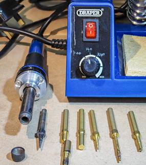
Figure
3.Soldering
iron, insert tips, variable temperature.
An important aspect of the iron was that it offered a straightforward method of
mounting it in a hobby drill press, as illustrated in
Figure 4.
An aluminium collar was turned to 20 mm dia to fit the drill press
aperture and then attached to a larger collar that secured the iron.
Screw holes were drilled and countersunk in the larger collar to match
the existing screws that held the iron together.
The particular Proxxon drill stand chosen has a simple means of locating
a matching small vice, very useful in locating a steady workpiece while pressing
the insert home. I had earlier
purchased an inexpensive two-heat hobby quilting iron which took tool heads on a
5.5 mm dia rod, and it was very promising.
But I found there was no satisfactory way to adapt the body of the iron
to the 20 mm press mounting aperture.
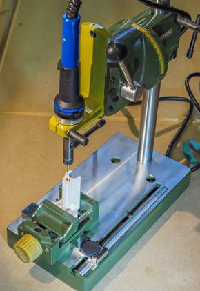
Figure
4.
Soldering iron in drill press.
Heat set threaded brass inserts come in a variety of styles and lengths, some
illustrated in Figure
5.
The UK isn’t well served yet, but McMaster-Carr is the best supplier in
the USA, otherwise the Lulzbot shop has a small range of the right stuff.
The better inserts have an entry section with a slightly reduced
diameter, allowing the insert to seat square on the hole before being heated and
pressed in, and they also have a cross-hatched knurl to resist both torque and
pull-out. I found an insert without
any reduced entry needed to be started by being held on the heated tip with
needle-nose pliers rather than resting on the plastic item.
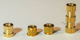
Figure 5.
Various heat set threaded brass inserts.
The spreader with its various inserts is illustrated in
Figure 6,
a production version printed in ASA filament.
ASA is resistant to UV which otherwise degrades most 3D thermoplastics
within a year or so, and this is important for equipment which is going to live
outdoors. 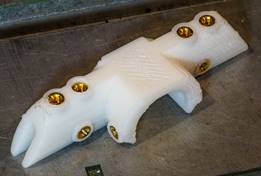
Figure
6.
Design #52 spreader body with brass inserts.
|
.htm_cmp_lghome010_bnr.gif)