![]()
![]()
![]()
![]()
![]()
![]()
![]()
|
|
|
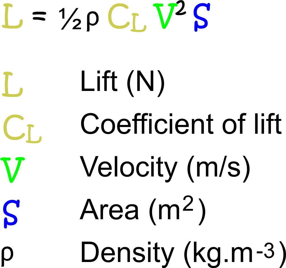
The engineering formula for lift is
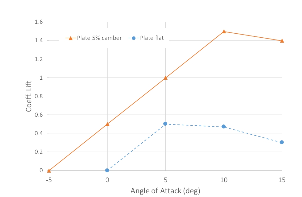
During the development of aerodynamics in the late 1800's and early 1900's the lift formula was known and used for practical engineering. The issue at that time was the appropriate value for CL, since the density, velocity, and wing area components of the formula were well understood. The real puzzle is giving an explanation for the formula -- why does it correctly calculate lift? The short answer is that, even today, there is no universally agreed theory for why a wing produces lift. Scientific American (July 2020) discussed the interesting gap between being able to calculate lift to pretty arbitrary precision, and not being able to completely explain why it occurs. Let’s see if we can fix that. Basic demonstrationPoke your arm out of the car window, and you’ll feel the wind pushing your hand up. Angle your palm a little more or a little less, and you’ll feel the upward push increase or decrease a little. We can agree that the amount of lift you experience is connected to the degree to which your hand deflects the wind. We can phrase that in more engineering language: the lift generated by a flat plate at an angle of attack, α, to a fluid flow is in proportion to α. The explanation is that the plate deflects the fluid down, and in an equal and opposite reaction the fluid pushes the plate up. After a little math, it turns out that the coefficient of lift, CL, increases by around 0.1 for every degree of α. Very roughly, when α = 5°, CL = 0.5 (of course, when α = 0°, CL = 0). Flat plateA flat plate works perfectly well as a wing or fin. The Lockheed F-104 has a ‘biconvex’ wing section – a thin four-sided diamond shape – so yes, it has a flat plate for a wing. But a flat plate generates significant drag and needs significant power when flying, and is unforgiving because it will stall at relatively low α such as 5°, which is the F-104 in a nutshell. Efficiency from rounding and camberIt was Wilbur and Orville who systematically tested cambered plates and found that curvature made the wing much more efficient. This improved efficiency was seen in three ways. First, rounding and cambering the plate, particularly rounding the nose, lowered drag for a given lift. They were the first to be able to go flying with very modest power. Second, stall could be postponed, or, the same thing, increased lift could be found with extended angles of attack, perhaps getting to CL = 1.5 and α = 10° before badly losing efficiency. Third, cambering the plate seemed to give better lift, perhaps CL = 1.0 when α = 5°. Interestingly, a cambered wing produces lift, perhaps CL = 0.5, even when flying straight and level, which might be said to be at no angle of attack at all. And this is where the puzzle is revealed. If it is the angle of attack which deflects the fluid and so produces lift, what is the explanation for the lift of a cambered wing, CL = 0.5, when α = 0°? And, how was the lift doubled at α = 5° by the cambered wing to CL = 1.0, where a flat plate wing only produced CL = 0.5? Angle of zero liftA cambered wing does not produce lift if it is angled ‘down’, that is, it is set at a negative angle of attack. Let’s consider that our cambered wing shows CL = 0 when α = −5°. We already know it shows CL = 0.5 when α = 0°, CL = 1.0 when α = 5°, and its extended performance of something like CL = 1.5 when α = 10°. These numbers are compared with the flat plate numbers in Figure 1. It turns out that the trend is the same for each plate, where we can see that lift does indeed increase by around 0.1 per degree of angle of attack, but starting from the angle of zero lift.
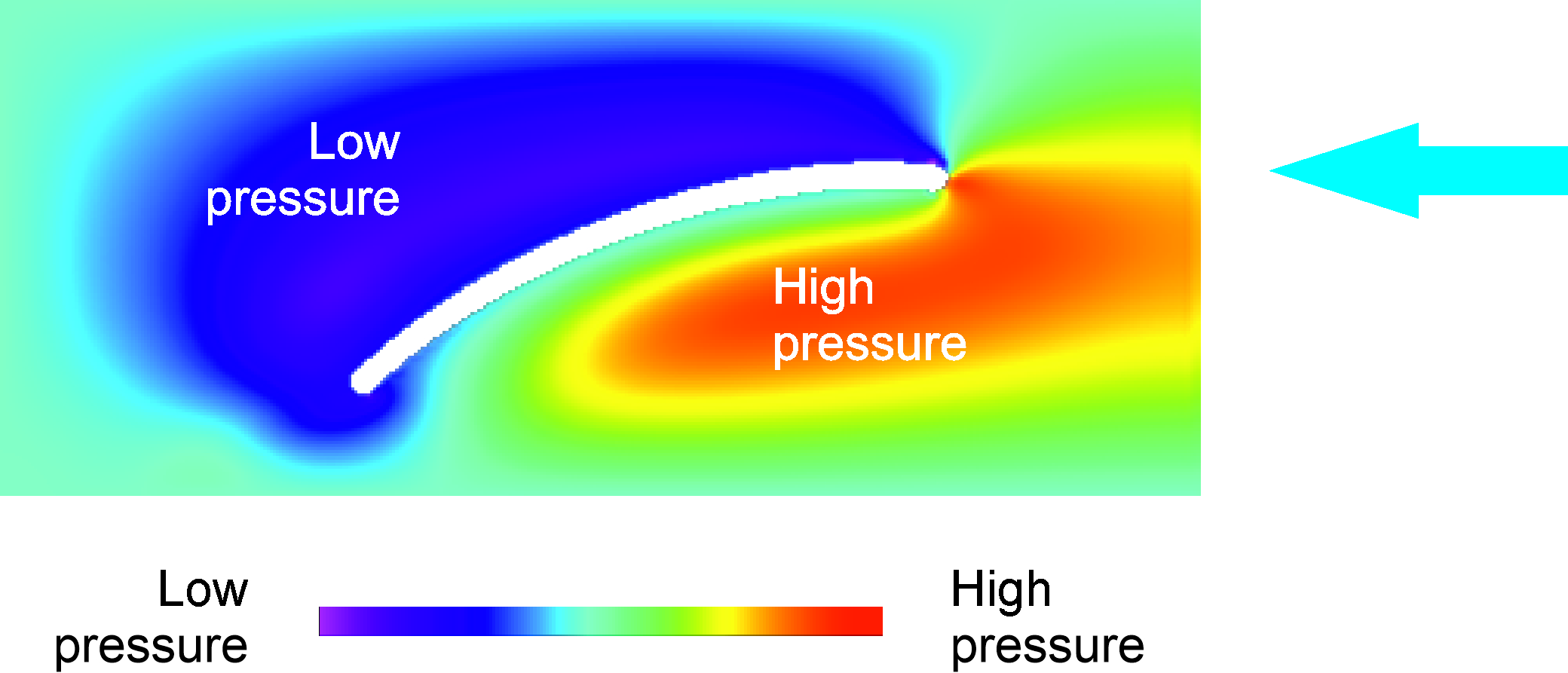
Figure 1. Flat plate and cambered plate illustrative section (2D) coefficients of lift, CL, for various angles of attack, α. We need to express these results more carefully. Angle of attack α is a geometric angle, and the wing is said to be geometrically level when α = 0°. However, a cambered wing when level has been deflecting the oncoming fluid for some time already. Only when our wing is set well below level at α = −5° is there effectively no fluid deflection and hence no lift. Provided we start from the initial position of no fluid deflection (we are ignoring turbulence here), we find lift increasing as the wing angles more directly into the fluid flow, exactly as expected. The real puzzle is to explain why camber in itself deflects fluid flow. Lift from camberLet’s repeat Einstein’s famous thought experiment, but instead of imagining we are sitting on a photon as it zips along at the speed of light, we imagine we are sitting with a bundle of fluid particles as we flow over the upper surface of a cambered wing. Starting from the nose, we are forced up by the curve of the wing. As the curve of the wing eases off, we stop being pushed up, and we travel straight and level for a moment or two. And now as the wing surface begins to drop away from us, where do we go? Well, we just want to keep going straight because of momentum and inertia. On the other hand, if we all just stop following the surface, we are going to create a perfect vacuum. So some of our bundle starts to follow the surface down, some of our bundle continues more or less straight on, and the remainder of the bundle spreads itself between those two. Technically, this results in decreased fluid pressure on the upper surface. A pressure decrease is the same thing as a partial vacuum, meaning that there is a suction on the upper surface of the wing, lifting it up. The amount of sucking – lifting – force depends on the amount of camber; more camber, more suction. Lift explainedDue to the angle of attack, there is downward deflection of the fluid flow. Technically, this is represented by an increase in fluid pressure on the lower wing surface, pushing it up. Due to camber, there is a decrease in fluid pressure on the upper wing surface, sucking it up. Add these two components together and the result is the lift produced by the wing. These pressure regimes are illustrated in Figure 2. This account of lift, pushing on the lower surface and sucking on the upper, is the point of view of Prof Mark Drela at MIT. Some nevertheless disagree, as SciAm explains.
Figure 2. Illustrative pressure distribution around cambered plate section at 10° angle of attack. Theories which "explain" the engineering formulaFrom considering the amount of fluid deflected by a flat plate, we can quite easily calculate the earlier approximation that CL increases by around 0.1 for every degree of α. (More exactly, it is 0.11, see the circulation theory of lift page.) Calculating the angle of zero lift for a cambered plate is not quite so straightforward, but there is a very rough rule of thumb that zero lift occurs, and hence lift starts being produced, at α = −t/c°, where t/c is the ratio of thickness to chord of the wing – the amount of its camber – expressed as a %. The cambered plate we considered earlier had t/c = 5%, and so zero lift was around α = −5°. Another way of looking at the same thing is to say that the addition to CL given by camber is very roughly 0.1 CL per % point of t/c, so the 5% cambered plate adds around 0.5 to CL above α = 0°. Similarly, the extension given by camber to the angle of attack at stall is very roughly +1° per % point of t/c, so 5% camber adds around 5° to the stall angle. Note the two other major theories of lift are Prandtl's lifting line theory and the momentum theory of lift. These three theories simply comprise different explanatory models for the same thing, the lift calculated as per the engineering formula. Worked calculation of liftWe can run through a worked calculation of the lift formula. We consider probably the most successful light aeroplane ever, the Cessna 172, and calculate the lift from the wings during cruise. The value of considering an aeroplane is that, by definition, the lift must exactly balance the weight, and since the weight is well known, it is immediately obvious if the calculation is correct. The Cessna weighs a nice round 1000 kg loaded, and cruises at around 100 km/h, or 50 m/s. The wingspan is 11 m, average wing chord is 1.47 m, and wing area is 16.2 m². Its wing section is a NACA 2412 (that is, 2% camber located at 40% chord and 12% thick) and the wing is rigged at +1.5° relative to the fuselage. This is an angle of attack of 1.5° when flying straight and level, and a little research at http://airfoiltools.com/airfoil/details?airfoil=naca2412-il shows that section CL = 0.42 for a Reynolds number of 500,000. We'll take the density of air to be 1.2 kg/m³. L = 0.5 * 1.2 * 0.42 * 50 * 50 * 16.2 = 10,206 N Since 1 kg = 9.8 N, this is 1,041 kg. Close enough to keep the 1,000 kg plane aloft. We could have obtained a good approximation for CL without reference to tables of lift by using the earlier rules of thumb -- 0.1 CL for every 1° angle of attack, and 0.1 CL for every 1% of camber. Our Cessna wing has 2% camber and 1.5° α, hence CL of 0.35 approximately. Not that far away from the tabulated 0.42. 2023-09-26 |
|
©2024 Lester Gilbert |