|
 I've
been very keen to make spreaders which are adjustable, particularly in terms of
the "V". This is about the 10th design I've come up with, after
help from Graham Bantock made me keep it as simple as possible. It is
pretty crude, but gives an idea of how this might work. The mast fitting
is, at the moment, free to ride up and down the mast. I may decide it
needs to be pinned in place. I've
been very keen to make spreaders which are adjustable, particularly in terms of
the "V". This is about the 10th design I've come up with, after
help from Graham Bantock made me keep it as simple as possible. It is
pretty crude, but gives an idea of how this might work. The mast fitting
is, at the moment, free to ride up and down the mast. I may decide it
needs to be pinned in place.
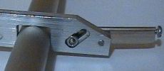 The
view on the right shows the spreader at maximum "V" angle of about 120
degrees, and gives a good view of the adjustment screws. To change the
"V" angle, the screws are slackened off and the spreader moved to a
new position. The "pivot" screw is tapped into the mast fitting,
and operates through a slot in the spreader. The "locking" screw
operates in a slot in the mast fitting, and has its nut running in a recessed
channel. The
view on the right shows the spreader at maximum "V" angle of about 120
degrees, and gives a good view of the adjustment screws. To change the
"V" angle, the screws are slackened off and the spreader moved to a
new position. The "pivot" screw is tapped into the mast fitting,
and operates through a slot in the spreader. The "locking" screw
operates in a slot in the mast fitting, and has its nut running in a recessed
channel.
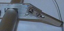
The recessed channel for the locking nut is shown in the picture
on the left, where the spreader is set at about 180 degrees. The shroud is
very simply clamped to the spreader by a screw, since the new SAILSetc
"aerodynamic" spreader can be tapped quite nicely for a M2 thread.
The slots are needed in the spreader arms and mast fitting in
order for the spreader length to stay roughly constant when the "V"
angle is changed. If the slot in the spreader is not present, as the
"V" angle is tightened up from 180 degrees, the shrouds are pulled
in. This may be undesirable. It turns out that the slot of the mast
fitting needs to be angled at about 45 degrees in order to keep the overall
spreader width roughly constant.
2018-06-23 |