![]()
![]()
![]()
![]()
![]()
![]()
|
|
|
The diagram shows an arm winch with two sheets, one for the jib and one for the main, attached at different positions on the arm, and exiting to deck at two separate points. There can be one deck exit, of course; and the jib and main could attach to the arm at the same place. The relevant measurements are as follows, and should be taken when the sail winch is set up at close-hauled: For the sail servo, "Aje" is the distance between the pivot axis of the arm, and the exit point of the jib sheet. Similarly, "Ame" is the distance between arm pivot axis and the main exit point. There is an assumption here, that the arm moves in the same plane as the exit points. If there is quite a gross difference in height between the arm and the exit points, the spreadsheet results will be less reliable. For the main sheet, "Mr" is the distance along the arm from the arm pivot axis and the sheet attachment. "Me" is the distance from the main sheet attachment point and the through-deck exit point. Similarly, for the jib sheet, "Jr" is the distance along the arm from the arm pivot axis and the sheet attachment. "Je" is the distance from the jib sheet attachment point and the through-deck exit point for the jib sheet. These measurements define the sides of two triangles, one for the jib sheeting, and one for the main sheeting. The relevant formula to calculate the angles involved is given by:
The spreadsheet calculates the "arm angle" at close-hauled, given your measurements. This angle is in fact the angle between the arm and the relevant exit point. You should check that this is about the angle you actually have. Set up the spreadsheet in the way described on the "Sheeting" page -- boom attachment points and so on, and the "start" values which can be calculated using the macro buttons. Update November 2020. David Kender has kindly provided an updated spreadsheet with macros that work with more recent versions of Excel. If the macro buttons don't seem to work, try kick-starting their goal-seeking by manually entering a guessed "Start" value which is quite large, say, twice the value of "Aje" or "Ame". The result is a sheeting graph, similar to the following:
Will Gorgen has shown me his set-up in his Fairwind. At close-hauled, his arm winch allows fine control of the main sheeting position while the jib more or less stays static. The following diagrams illustrate his ideas. Will says the arrangement "allows me to 'dump the main' in puffs while keeping the jib in to keep the boat from rounding up".
I've now developed a second arm winch spreadsheet (50 kb) which models this set-up: pulleys on the arm, one for the main, one for the jib, and a bulkhead attachment point any distance away from the sheet exit point to deck. The extra measurements needed are illustrated below. The diagram shows one sheet, the jib sheet, with extra measurements "Ajb" and "Jbr"; similar measurements are needed for the main sheet, called "Amb" and "Mbr". If there is only one pulley, then "Mr" = "Jr". If in fact it is a control line attached to the arm, such that the sheets are attached to the line above deck, then "Amb" = "Ajb" and "Jbr" = "Mbr", as well as "Ame" = "Aje", and "Me" = "Je".
The "over centre" arrangement that Will's set-up shows can be used in one of two ways. The first way is to use it to give fine adjustment of jib sheeting angle while the main remains more or less constant at close-hauled. (This reverses the colour of the sheets shown in the "over-centre" diagrams -- the jib is now the red line, and the main is the blue line.) In this case, the main has great trouble "catching up" to the jib for reaching. And when it does, it then must over-shoot for broad reaching and running. This is shown on the following graph. We see that the main hangs around at a sheeting angle of about 4 to 7 degrees while the jib sheets between 13 and 20 degrees. To get this result, the jib boom sheet attachment radius needs to be much greater than the main's, perhaps 130%, and the deck fairlead needs to be well aft as well.
A second way to use the "over centre" arrangement is as Will uses it, to allow the main to be "dumped" while the jib doesn't move very much. In this case, as shown by the graph below, quite a lot of stick movement is needed before the jib begins to sheet out, at which point the main then runs pretty much parallel with the jib to the dead run. We see that the jib holds a sheeting angle of around 15 to 18 degrees while the main sheets out from 5 to about 12 degrees. To get this result, it turns out that the jib boom sheet attachment radius must be considerably shorter than the main -- perhaps only 85% of the main's sheeting radius.
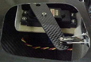
Play with the spreadsheet to see if you can improve on these results. It seems to me, however, that we aren't going to see an effective "jib trimming" arrangement using these methods, only a useful "main dumping". Ken Binks has kindly given me a photo of his set-up in his "Isis" IOM. The winch arm is in view, with the pulley at the end. The photo shows the fully "out" position of the arm for a dead run. For more details, please contact Ken at K.Bits.. This is his description: The arm radius is 90mm from the centre screw to the tip. Total arm length is 120 mm. The pulley is 80 mm from centre (though I think it should be 85mm). This gives a total sheet travel of 260 mm or so. The servo is fully programmable: throw, direction, speed, failsafe setting, and deadband. At 6 volts, speed of operation is 0.13 sec/60 degree. Torque is 19 kg/cm. The holding power of digital technology is such that the best description is 'gearbox seized'! Servo size is 59 x 29 x 52 mm excluding lugs and arm. I think the 'footprint' covered by the servo and arm is approx 120 mm by 160 mm to accommodate 120 degrees of arm swing. Battery consumption worries were an unfounded concern. After the recent Brentwood event using an 1100 mAh NiCd, when tested on load afterwards it still held the top green LED with 2 hrs 30 mins on the clock, and as you know there was a lot of top-end 'A' rig at that event. Servo doesn't even get warm which is excellent. I now believe the power is more than sufficient for a Marblehead, and I have one customer looking to fit two 2 into an 'A' class. I'm very confident it will be 'fit and forget' for reliability, but time will tell. My set up has approx 120 deg movement and a superb 'silky' close hauled response. Close-hauled the arm is within 10 deg of straight ahead, and it moves back to 40 deg past abeam for a dead run. A closed loop sheeting system is not practical, so I tension the line with elastic. From fully sheeted-in to fully sheeted-out takes approx 0.25 sec !!! The servo has an all-metal gearbox, large dual ball-raced output shaft, large exposed heat sink on motor, and all case joints and screws 'O' ringed for water resistance. It has 6 case screws instead of the usual 4. It is supplied with a metal arm which forms the base of the carbon extension I have made. K Bits (that's me) will be able to supply the special arm extension and the pulley attached to it for around £15. The servo costs £59.95. A real benefit of this servo is that you get superb sheeting performance using a very basic 2 channel AM system, bringing the cost of a really competitive sheeting set-up in an IOM right down. There is a separate programmer for £110 (it isn't vital) but customers' requirements can be programmed by K Bits.
There is one aspect that needs to be mentioned about the digital Hitec 1/4 scale servo used by Ken as an arm winch, and that is that it's heavier than the "normal" size drum winches from Whirlwind, Futaba, Hitec, and so on, though no heavier than the RMG drum winch. 2020-11-11 |
|
©2025 Lester Gilbert |